| read the discalimer | Pioneer SA series? | inside This amplifier | what about the Circuit? |
| the Wire Wrap | the Damage | reforming supply Capacitors | fixing Supply |
| fixing the Amplifier | Check before power on | the first Power On | the Modify |
| some Measure | Conclusions | file Download | . |
All trademarks mentioned and links are presented here for informational purposes only and to confirm statements made by the author. The author of these pages DOES NOT receive any remuneration from the mentioned brands and the listed links.
In any case if you decide to use the suggestions on this page you do so at your own risk. Repairing electronic equipments, even just opening it, can put your life at risk, so don't do it.
If you do not accept and/or not understand the statements in this disclaimer, written in blue, exit this page immediately.
Everything exposed in this web page is only a suggestion, probably you won't obtain the aim from you prefixed following it.
A true collector is looking for a) original items without any replaced parts, b) or if a Critical Restoration has been done that it is possible to go back to the original version. Lacking the previous 2 statements the object (not only for me) has a value of zero euros.
Here we could include the history of Pioneer, or at least the history of the SA-xxx series, but that would take away space from the reconstruction of this integrated amplifier.
If you are interested in the list of models, here are some interesting links:
To be clear, we do not recommend purchasing a vintage Pioneer amplifier, but we cannot advise against it either. The problem is that prices are out of control for all vintage items. Even though they were good devices, the prices being asked for them today are crazy.
Just as an example, €2,900 for a Pioneer C21+M22 (Feb. 26) or €1,500 for a Yamaha B2 (Dec. 25) or, worse still, €4,000 for an unreliable Sansui 20000 (Nov. 2025), more then €1900 for Accuphase E-202, are high prices for devices that are excellent when new but may need to be completely rebuilt inside (see the section on capacitors here) or, worse still, have been tampered with but are sold as immaculate.
However, after walking around audio fairs and seeing CD players sold for €28,000, we have some doubts about a market that exploits our weaknesses. Not to mention the $108,000 cable between an amplifier and speakers. Perhaps they new sellers/brands are right: "They have the money, so let's take it from them".
If you really want to make a crazy purchase of a vintage item, I recommend NOT turning it on. The best thing would be to pick it up at the seller's house and see/hear it working. Nothing can be said about what will happen in a month, but at least "it works now". Fortunately, my friend did NOT turn on the Pioneer!
If you buy it switched off, take it to an honest technician to have a look inside and switch it on for the first time.
We are interested in this Pioneer SA-7800, back to 1979, its history, its visible and hidden defects, its internal components (which we hope are original) and any parts that have already been replaced.
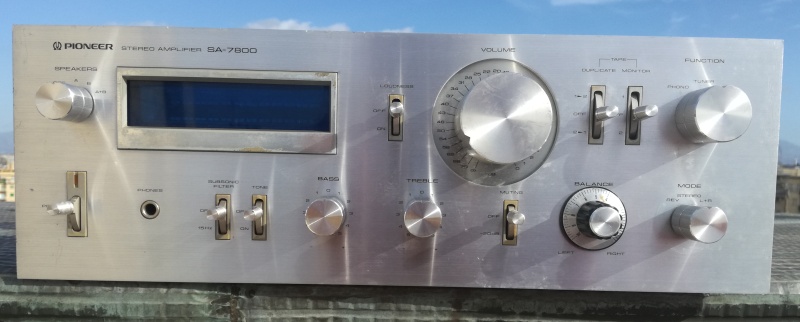 |
| Fig.1, Our SA-7800 seen from the front. From this photo taken from a distance, you cannot see all the scratches and marks on the faceplate and even on the knobs, nor the damaged display frame, but you can see the missing knob |
Let's open it up (the screws are original) and take a look inside, and here are the surprises, first in the photo below.
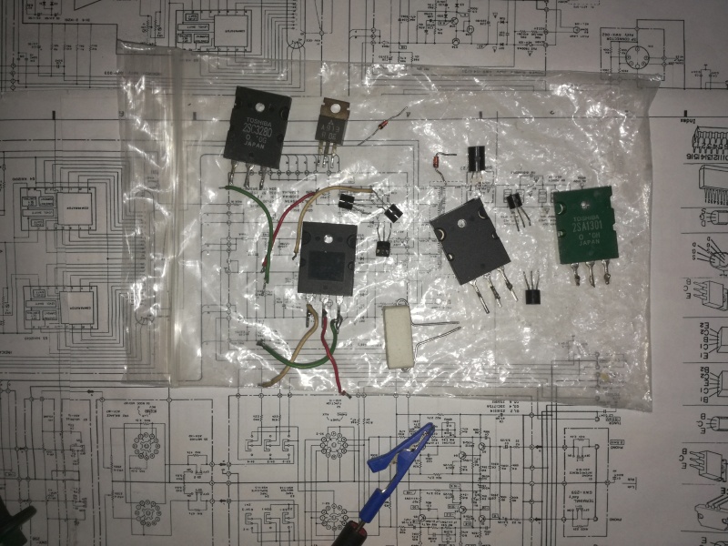 |
| Fig.2, Inside, we find a plastic bag with some components in it. What are they for? Which ones? Are they broken? |
Here is the list of components in the envelope:
All the broken ones can also be found on the wiring diagram, apart from the 2SC2240? The working ones are not on the schematic, but the 2SA1301 and 2SC3280 are original, vintage, Toshiba power transistors, why here?
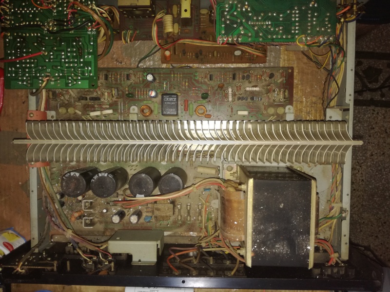 |
| Fig.3, here is a photo of the interior, which is very dirty. But that's not all. You can see the dirt more clearly in the high-resolution photo |
It is not clear from the photo, but at the bottom of the device there is something dried up, like a Cola or Chinotto liquid that may have fallen through the ventilation slots on the lid. Let's take a closer look.
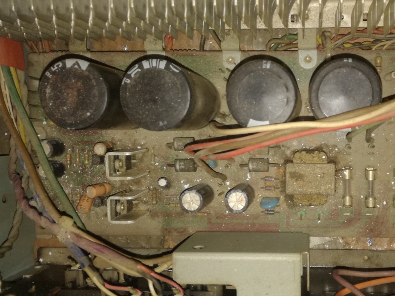 |
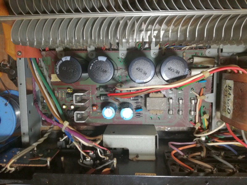
| Fig.4, let's take a look at the power supply section. You can see the second transformer on the right, the 4x 8000μF/50V Nichicon capacitors in the centre, and the stabilisation circuit on the left. Some liquid has been spilled and there is a lot of dust |
Unfortunately, this means dismantling the entire front panel, the bottom panel and anything else that can be removed, covering the transformer with plastic bags and adhesive tape, and washing it on the terrace with a garden hose (then flush with distilled water). All this has to be done early in the morning on a nice sunny day.
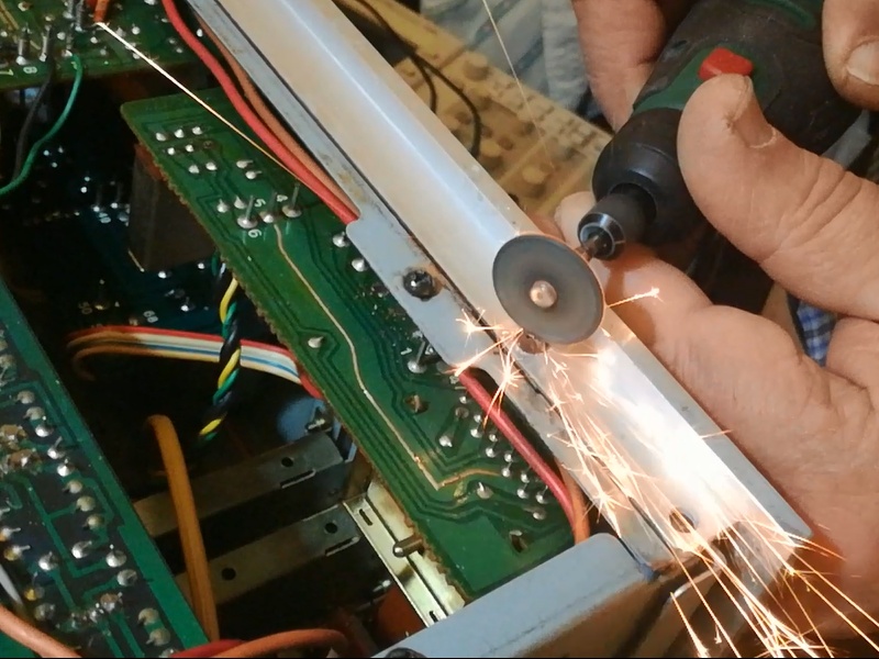 |
| Fig.5, removing the rusted bolts from the bottom was easy, but the ones securing the front panel from underneath are stuck. Using a flame torch is not an option, so we will cut off the heads. Here is a video of the surgical procedure (.MP4, 7.9MB) |
Once the front panel has been removed, which will then need to be cleaned and restored in some way, we can see the damage caused by the spill.
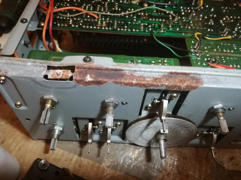 |
| Fig.6, to remove the panel, we had to use force, so even the frame, after careful cleaning, will need to be straightened. What a disaster! Then we will try to remove the screw, which now has no head, to secure the front with a nice screw from another Pioneer |
Surely removing the remains of that screw without causing further damage is a complex task.
First, we find the service manual, or rather, we discover that there are 3: one complete manual and 2 additional for the sub-versions.
As always, in the Download section you will find all the project files, services, diagrams, etc.
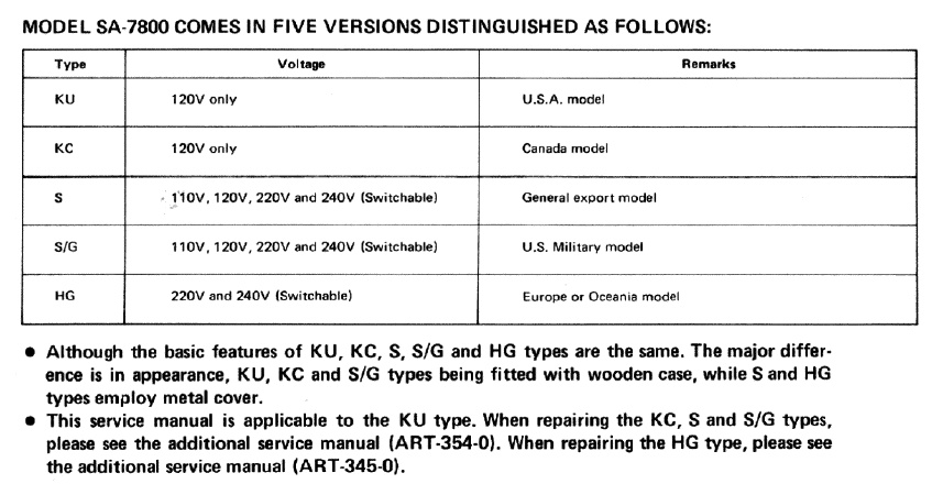 |
| Fig.7, the service describes what other documents we need depending on the version. Ours is HG, and the "additional" one is found. Fortunately, we do not need ART-354-0, which is truly impossible to find |
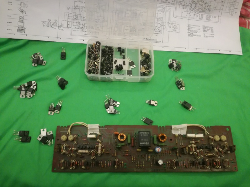
Where do the components in the plastic bag come from? Are they replacement parts? Let's take a look at the PCB.
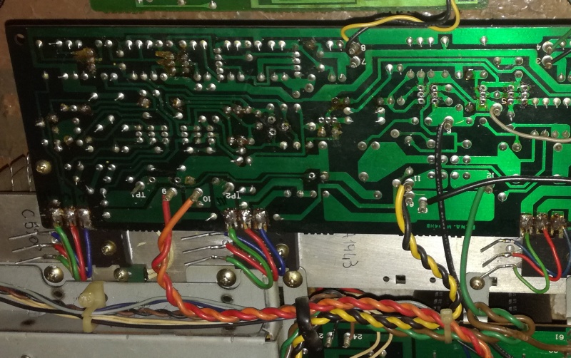 |
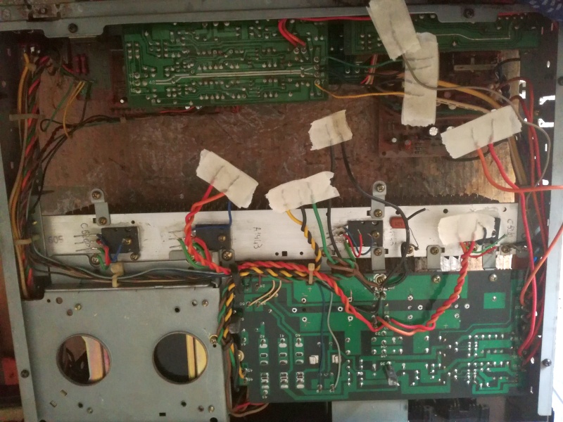
| Fig.8, You can immediately see that some components are missing and that repairs were left half-finished. We note that transistors 2SC5200 and 2SA1943 are fixed to the heat sink and soldered with colored wires, an excellent choice. Fortunately, the amplifier was NOT turned on. Here is the original photo. |
However, the components in the envelope are insufficient to fill all the gaps, some were left on the repairer's table.
The presence of the broken 2SC2240 confirms that the production series is much larger than stated by the service manual. But which part in the diagram was replaced with 2SC2240?
Manufacturers secretly replace parts for improvements and economic savings. This is confirmed by the Toshiba 2SA1301 and 2SC3280 power transistors found in the envelope. One has colored wires still attached, these were the original power transistors.
The famous pundits, geniuses, barkers, and shouters will then explain to us, from the height of their incompetence, that the XUZ version is better than the SWA, obviously without knowing how a lateral FET works or difference with vertical FET.
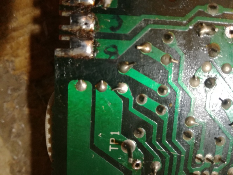 |
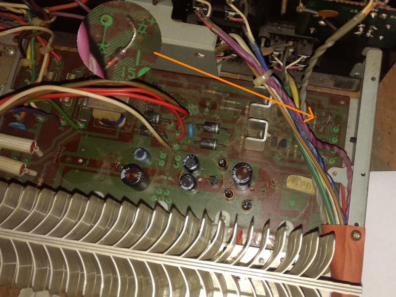
| Fig.9, and here we are already repairing. The ENTIRE device must be inspected with a magnifying glass to look for manufacturing or usage problems. Here, in the centre of the photo, is a badly bent reoforo that we will have to be repaired. Does it touch? Does it not touch? It certainly cannot be left like this (it must be repaired immediately) |
You should only spend half an hour at a time on research (I set an Alarm Clock) because after that your eyes start to strain and you miss some flaws.
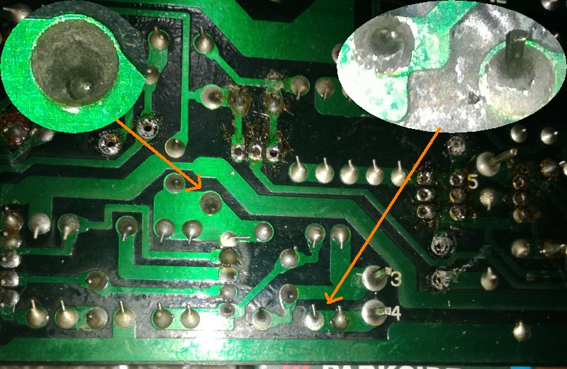 |
| Fig.10, this is a typical fault after 30 or more years of use, or in this case almost 50 years: defective solder joints. They are difficult to find. You need a magnifying glass and a torch to change the angle of illumination, as well as time and patience (and these can be repaired immediately, otherwise you'll forget about them) |
We were talking about buying vintage items. It can be done, but expect problems like the one in fig. 10. And don't blame the seller, it worked at his house, but the car journey didn't do it any good.
Years ago, I repaired a Krell KSA-200B belonging to a friend who was an editor at Stereoplay. It took months of work. There were hundreds of them (see fig. 10). The thermal paste had melted, and the resistors were still working but burnt out.
But what would you expect to find inside a class A amplifier that gets so hot?
Krell in the US ... wonderful, they sent me all the original components, even the plastic screws (but only service manual cutouts, defective areas only, and calibration).
I still dream about it once the job is done, but starting over on another similar one is a nightmare.
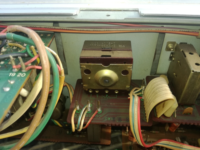 |
| Fig.11, there is something good about it. It may not be a Noble, Penny & Giles, A&B, or TKD, but it seems to be a good potentiometer, unlike many other brands that use ones that look like shirt buttons |
Potentiometer PCW-113-0 , 117Y100KΩX2 probably an Ohmite.
Remember that the entire device uses wire wrapping for connections.
But what exactly is wire wrapping? It is a technique for twisting two wires together that originated in jewelry making as early as 2000 bCE and is still used today.
The electronics industry adapted it in the 1950s. It was a method of reducing soldering. A machine wraps stripped rigid wire around a square pin.
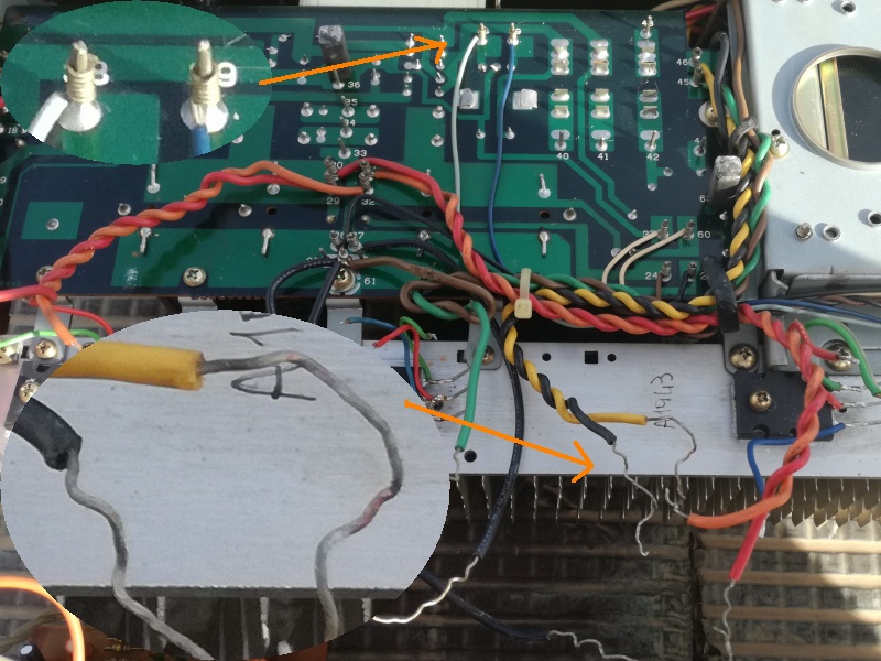 |
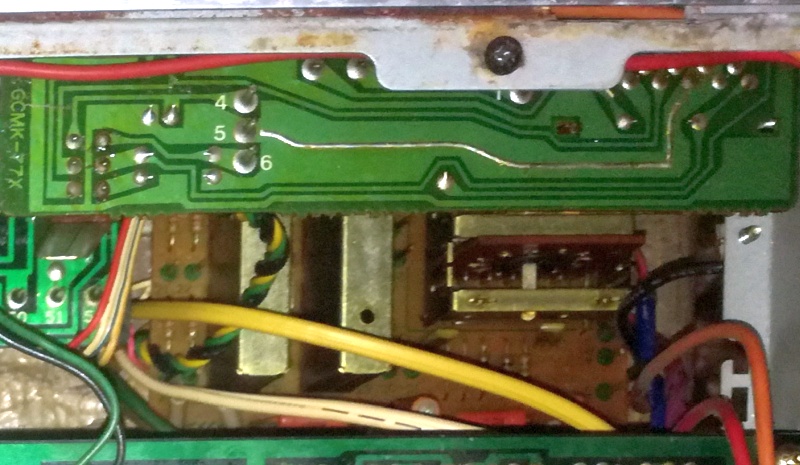
| Fig.12, it could have been worse. If you slowly unravel the wire wrap, you can see a little oxide on them, but only in a few places. It seems that the contact is still good, at least on the ones that have been dismantled. With Mouse Over we can see other wrapping near potentiometer. |
However, after 30 years of use, moisture and oxygen get between the pin and the bare wire. The resulting oxide reduces contact to the point of preventing it.
Some people solder over it to repair it, but that makes things worse because the tin does not get between the coils and does not stick to the oxide. This requires unwrapping the wire. However, we will discuss that later since all the contacts on the final PCB are made this way.
But how do you repair an audio amplifier? You can find a long, explanatory article on Rod Elliott's website, but he forgot to mention the use of the Hameg HZ65-3. To avoid the nightmare of repairing a CD, we'll leave it all until tomorrow (but in the meantime, you can read the 216 pages of Ken Clements' book).
One of the faults could be the wire wrap itself, but we will only know for sure when everything else is working.
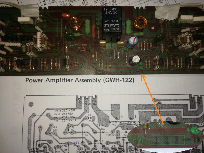 |
| Fig.13, first, we print out a large copy of the PCB design for the amplifier stage and look for the codes of the missing components. Fortunately, we have the design for our GWH-122 |
By searching the circuit for the missing components on the PCB and finding the corresponding ones on the circuit, we can narrow down the fault, then discover some resistors that are still present but burnt out.
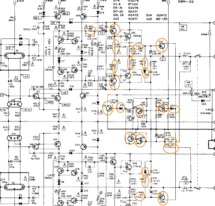 |
| Fig.14, a circle on all faulty components, even the power transistors were faulty, but here we find them already replaced and installed. In Fig. 8, we see the power transistor soldered to the circuit. Here is the enlarged drawing |
It seems that the left channel has broken, but strangely it has taken the entire protection circuit with all its transistors and diodes with it.
Since we cannot study the original fault, but only what remains, the repair is really difficult.
| code | original fitted |
direct replacement |
substitute | code | original fitted |
substitute | code | original fitted |
substitute |
| Q23 | 2SC1913 | . | 2SC2073 | R51-R53 | 220R 1/2w | . | R66 | 1K5 1/2w | . |
| Q25 | 2SA913 | . | 2SA940 | R57 | 150R 1/2w | . | D22 | 1S2472 | BAV20 |
| Q27 | 2SC1914A | 2SC1890A | 2SC2240 | R59 | 150R 1/2w | . | D21 | 1S2472 | BAV20 |
| Q33 | 2SC1384 | . | . | R61 | 0R22 2w | wirewound ceram 3W |
D24 | 1S2472 | BAV20 |
| Q32 | 2SC945A | 2SC1914A | . | R63 | 0R22 2w | wirewound ceram 3W |
D25 | MZ-130 | WZ-130 ZPD13 |
| Q30 | 2SC945A | 2SC1914A | . | R65 | 1K5 1/2w | . | C39-C42 | 8000μF 50V | 10000μF 63V 105°C |
| Q29 | 2SC945A | 2SC1914A | . | R67 | 15K 1/2w | . | C29-C30 | 220μF 80V | 330μF 100V |
| Q31 | 2SA733A | 2SA940A | . | R68 | 15K 1/2w | . | C35-C37 | 47μF 63V | . |
| Q28 | 2SC1914A | 2SC1890A | 2SC2240 | R66 | 1K5 1/2w | . | C34-C35-C48 | 4.7μF 50V | . |
| TP1-TP3 | 2SC2525 | 2SC3280 | 2SC5200 | R74 | 15K 1/2w | . | C25 | 330μF 6V | 330μF 10V |
| TP2-TP4 | 2SA1075 | 2SA1301 | 2SA1943 | R75 | 15K 1/2w | . | C26 | 100μF 50V | . |
| C39c-C42c | not | not | 0.1μF 100V POLYxxx |
R68 | 15K 1/2w | . | C39b-C42b | not | 100μF 63V 105°C |
The components chosen for repair are highlighted in yellow. It is preferable to use original parts, thanks to the 2 sellers (fortunately, given the difficulty of finding 2SC1384), or substitutes.
We will obviously also change the mirror component, for example R53 when we replace R51.
A word of advice for anyone who wants to try their hand at repairs: NEVER accept an item that has already been tampered with and that they have not been able to finish.
 |
| Fig.15, we don't know if the various switches and potentiometers will also need to be repaired, we'll find out when we turn it on for the first time |
And where can we find the original transistors, or at least the replacements mentioned in the service manual? As my friends know, I usually buy from 2 distributors of audio and Hi-Fi parts in Germany and from a well-known international distributor.
 |
| Fig.16, they don't pay me, they don't give me discounts, they don't sponsor me: but we need to highlight companies that are struggling to stay in the market, distributing original (not fake) products at reasonable prices. Kudos also for their courtesy in transactions |
On forums, I often see complaints and even insults directed at my 2 famous German suppliers. Those who write are people who are naturally argumentative and hostile. Instead of being grateful for the availability of genuine components, they complain because there is a delay of a few days and because only half of the order has arrived (without mentioning that the other half will arrive later, free of charge).
And maybe some strange people even protest against these two.
After carefully reading the reviews, I realised that those reporting negative experiences are not repair experts but hobbyists who think they can solve their problems through a distributor (who is actually there to sell).
In Fig. 4, we see the four 8000μF capacitors, and we immediately notice their proximity to the long cooling heat sink.
This is a typical problem for designers, who have two alternatives: a) place the capacitors near the final transistors to improve current flow, or b) place them further away to protect them from the heat generated during operation.
An interesting example of this logic is the Audio Research SP8 family. In the first versions, all the capacitors were on the component side, but by issue 7 almost all the capacitors had been moved to the underside, away from the heat that rises.
Now we need to dismantle and measure the four capacitors for comparison with the datasheet.
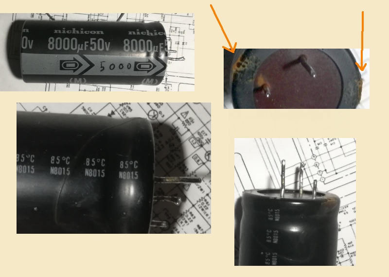 |
| Fig.17, Nichicon 8000μF 50V N8015 85°C, 3 pinout. No datasheet can be found, after 45 years! Note the drops of glue that secured it to the PCB; we will put them back on the new ones |
Even the value today is strange: you can find 8200μF, but not 8000 (like the 160μF of my Marantz 7C, which is almost impossible to find).
We solder all the negatives together with a 1 mm wire, which we will need later, and then measure the four capacitors one by one.
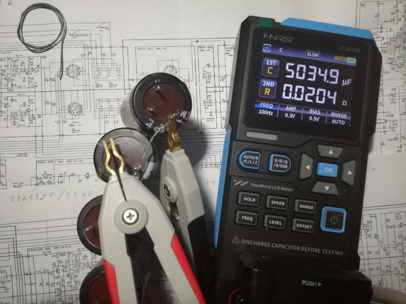 |
| Fig.18, the LCR meter allows us to measure various parameters of the capacitor at various frequencies. We choose 100Hz |
After carefully self-calibrating the instrument (better than the simple calibration described in the manual), we measure.
| . | capacitance (C) | dissipation factor (D) |
quality factor (Q) | phase angle (θ) | equivalent series resistance (R) |
reactance (X) |
| C39 | 5035 | 0.058 | 17.13 | -86.6 | 0.0204 | -0.32 |
| C40 | 3699 | 0.052 | 19.34 | -87.03 | 0.022 | -0.321 |
| C41 | 4492 | 0.055 | 17.91 | -86.6 | 0.0196 | -0.348 |
| C42 | 3749 | 0.054 | 18.77 | -86.88 | 0.0227 | -0.42 |
That's not quite right. The best one measures 5000μF instead of the 8000μF on the label. Before replacing them, let's try to regenerate them.
Capacitor regeneration, reforming
There are thousands of pages on capacitor reforming, some of which are written by audiophiles trying to save old equipment. Many of these pages describe industrial processes where capacitors are essential, and failure can cause serious problems. Let's leave impulse techniques aside and focus only on those involving DC voltage.
By the way, in the downloads section, you will find a document from Cornell Dubilier (wonderful capacitors) on how a capacitor is made, and on page 7, it talks about reforming.
If you are working with voltages above 50V, it becomes dangerous. Reforming a 47μF 500V capacitor puts your life at risk due to electric shock and explosion. DO NOT do this.
We have already connected all the negatives; now let's put a 100 ohm R in series with the positive and build a small half-wave power supply with a very small filter capacitor (10μF) to leave plenty of ripple.
We will use a Variac to power the 230-24+24 transformer so that we can regulate the voltage on the capacitors.
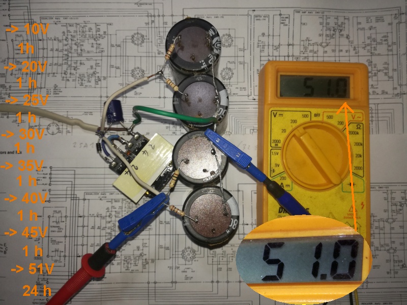 |
| Fig.19, the 4 capacitors reformning, on the left there is the list of voltages and times. You can perhaps see the single 1N4007 diode to leave a little ripple |
Each time the applied voltage changes, the voltage across the four resistors must be measured immediately, i.e. the leakage current. The same must be done after one hour and the results compared.
 |
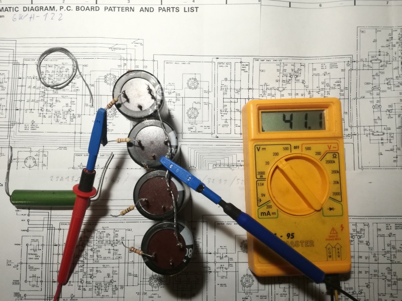
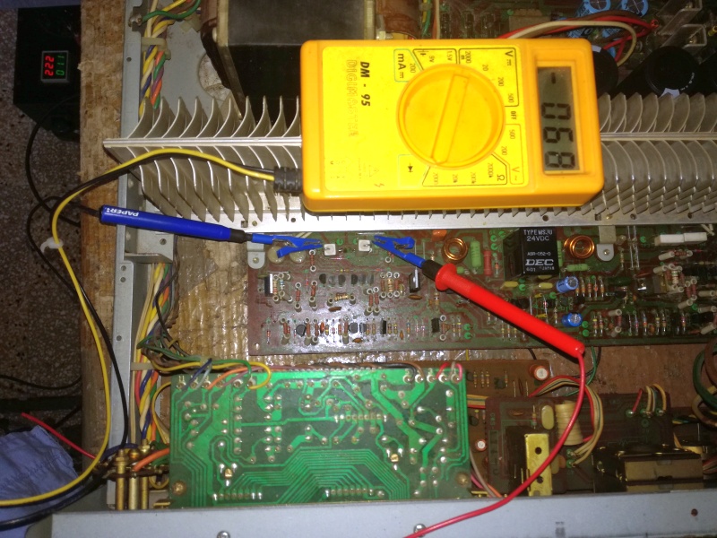
| Fig.20, we measure the voltage across the 100 ohm resistor. A leakage current of 1 mA produces a voltage of 100 mV, which is easily measurable |
How much should the leakage current be? Preferably 0mA but I suggest never more then 1-3mA in reforming. If we had the capacitor datasheet, we would find the values also as a function of temperature, but the datasheets for the Mallory capacitors used by the McIntosh MC30 cannot be found, like those for the capacitors from 50 years ago.
After 24 hours, do not switch off the variac immediately, but first quickly unsolder the four resistors and leave the capacitor disconnected.
 |
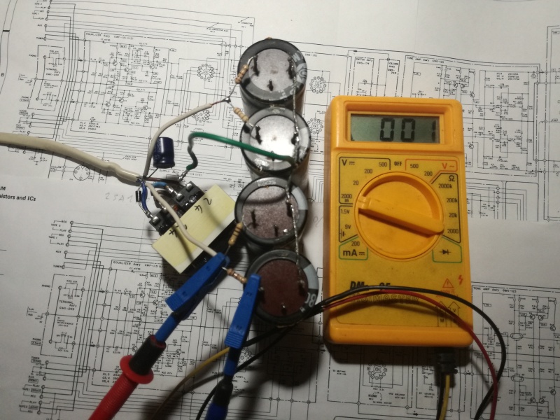
| Fig.21, measurement of residual voltage after 2 hours, damn bleeders that kill capacitors every time I turn off a device. But let's look at the green resistor we'll need to discharge them before measuring |
During reforming, I strongly recommend measuring the temperature of the case, perhaps with an inexpensive IR thermometer. The temperature must not rise.
As soon as you disconnect the power supply, touch the case. It should be cold, otherwise throw away the capacitor without further checks.
About bleeder ... if you send all the political rejects, runaways, and friends of friends to Europe, what kind of rules and laws do you think will come back? The bleeder resistor, invented by idiots for idiot technicians. If you don't know that the capacitors in an amplifier with a pair of Amperex 845s can still hold 1000 V even after being turned off for a day, then quit this job and go work as a pizza maker and watch how the oven burns.
| . | capacitance (C) | dissipation factor (D) |
quality factor (Q) | phase angle (θ) | equivalent series resistance (R) |
reactance (X) |
| C39 | 5055 | 0.062 | 16.32 | -86.5 | 0.0193 | -0.317 |
| C40 | 3751 | 0.059 | 16.68 | -86.62 | 0.025 | -0.424 |
| C41 | 4573 | 0.062 | 15.93 | -86.43 | 0.021 | -0.344 |
| C42 | 3862 | 0.067 | 15.06 | -86.18 | 0.028 | -0.416 |
Looking at the values, and Fig.19, the capacitors seem fine, leaking less than 1 mA even at nominal voltage, no self-discharge even after hours, but ....
The capacitance value has not been restored with reforming, the best we have achieved is +3% on C42.
The list is getting longer, we have to change these capacitors, but this time we will use 105°C ones, and also all those in the supply section that have been flooded by some colored drink.
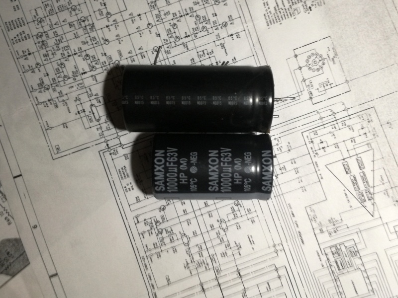 |
| Fig.22, instead of using boutique capacitors, we choose 105°C long life, low ESR, for high ripple design, used in switching power supply |
Since they are snap-in type, you will need a few tricks to fix them in place of the originals.
It seemed that the fault was confined to the amplifier stage, or rather to the final power section, but over the years the power supply had also been affected.
And we have many doubts about the famous fluorescent display, fingers crossed.
Fixing the power supply section
Let's start by dismantling all the electrolytic capacitors in the power supply stage. We have already removed and measured the large filter capacitors.
 |
| Fig.23, with the removed capacitors resting on the printed circuit board, we can also see a Zener diode detached from one side |
Before we forget, let's measure the Zener D31, which according to the diagram is an XZ-060, using a very useful tool (why don't they pay me for these suggestions?).
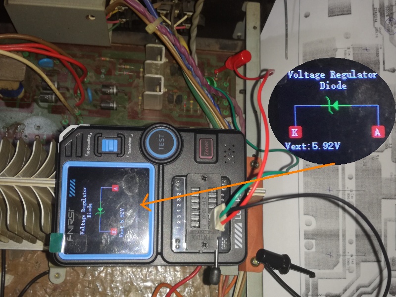 |
| Fig.24, using two clips, we measure the Zener diode, which should be 6V 1/2W. It appears to be in excellent condition |
How healty are the electrolytic capacitors we removed? A measurement can provide us with statistical feedback on the "health" of all the dozens of others installed in the amplifier.
| . | value in μF | measured capacitance (C) |
dissipation factor (D) |
quality factor (Q) | phase angle (θ) | equivalent series resistance (R) |
reactance (X) |
| C29 | 220/80V | 211 | 0.097 | 10.39 | -84.42 | 0.074 | -0.7538 |
| C30 | 220/80V | 212 | 0.109 | 9.72 | -83.80 | 0.081 | -0.7498 |
| C36 | 47/63V | 42.8 | 0.130 | 7.639 | -82.53 | 0.523 | -3.955 |
| C37 | 47/63V | 41.7 | 0.135 | 7.39 | -82.31 | 0.557 | -4.110 |
| C33 | 100/10V | 110.2 | 0.349 | 2.846 | -70.55 | 0.512 | -1.446 |
| C28 | 2.2/50V | 2.09 | 0.052 | 18.866 | -86.92 | 4.199 | -77.23 |
| C34 | 4.7/50V | 4.55 | 0.088 | 11.33 | -84.89 | 3.139 | -35.02 |
| C35 | 4.7/50V | 4.47 | 0.074 | 13.49 | -85.74 | 2.649 | -35.57 |
| C48 | 4.7/50V | 4.45 | 0.082 | 12.15 | -85.26 | 2.977 | -35.82 |
Considering that the old capacitors were sold with a capacity of -20%, +50%, the dismantled capacitors are still in good condition.
9 capacitors give us some statistical inference about the quality of all the others. We will replace these dismantled ones, but not the others.
 |
| Fig.25, all capacitors in Table 4, new, installed |
The four large filter capacitors, as well as C29 and C30, were glued with two drops of neoprene glue, as they were originally.
Before applying power, however, we must insulate all the flying wires that we disconnected.
 |
| Fig.26, the masking paper tape is sufficient to insulate all the wires we have disconnected, both the power wires and the signal wires |
There are various methods for turning on a newly repaired device, the two most common being: a) one or more light bulbs connected in series to a power supply wire, b) a variac with instruments for measuring voltage and current upstream of the device.
In both cases, the aim is to limit/measure the current consumed by the device.
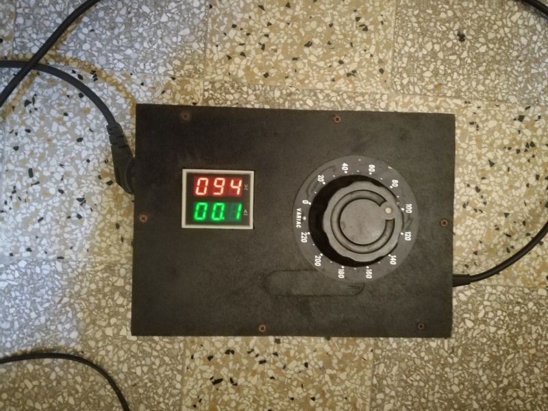 |
| Fig.27, a magnificent Variac from the Italian company Belotti, 0-230V, 2.5A. A truly useful vintage item inside my beautiful handmade container |
Do not start at 94V but at 0 and increase slowly, measuring the voltages as shown in the wiring diagram and checking the current absorbed.
 |
| Fig.28, with the volts in fig. 27, we obtain 20V on the filter capacitors |
The schematic shows +46V and +46V on the 8000uF capacitors, +63V and +63V on the 220uF capacitors, and +48V and +48V on C36-C37, the stabilized power supply.
 |
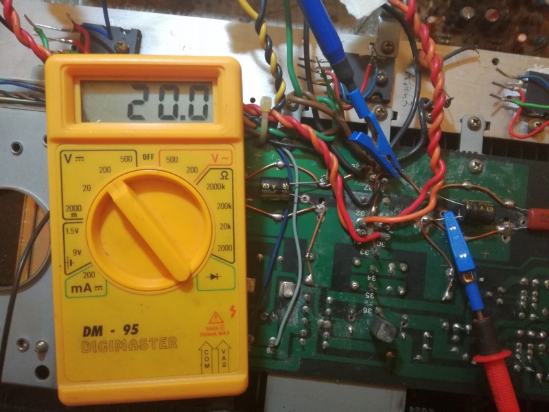
| Fig.29, with 218Vac we get over 47V, turn down the variac |
If we had connected the Pioneer directly to the mains, perhaps with 228V, we would have greatly exceeded all the expected values, since there is no final stage that consumes power and puts a little strain on the power supply.
Be careful with all vintage equipment, as almost all of it is built for 220Vac, but today it is easy to find voltages of 230V and even 240V, which can really put them under strain, even for those that are 50 years old.
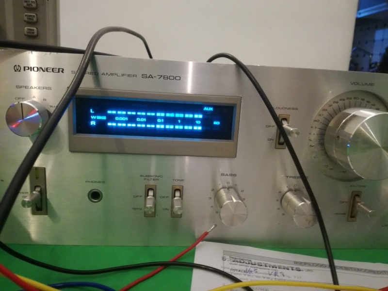
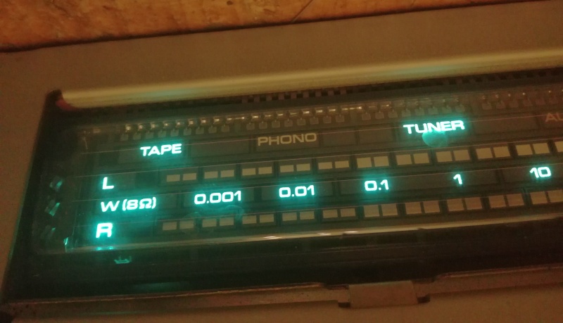 |
| Fig.30, great news, the fluorescent display is working. We don't know if it measures watts accurately, but at least it turns on |
I think it's time to fix the chaos they've created in the final stage.
After years and years of repairs and rebuilds for the amplifiers of friends and acquaintances, I have a small stock of original parts in my drawers (often when replacing a broken component, I also replace its counterpart, even if it is still in good working order).
 |
| Fig.31, if there were only 1 or 2 broken transistors, we might be able to find the original, but the list in Table 1 is too long. We will have to ask the two suppliers already mentioned |
Since we need to replace the capacitors, we are spending some time researching, not looking for boutique products, but quality ones.
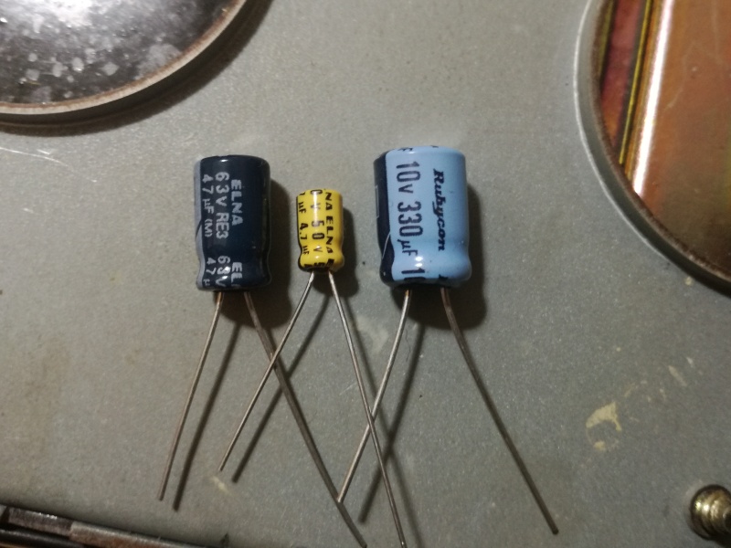 |
| Fig.32, we find brand-name capacitors, renowned for their quality, such as Rubycon, Elna, etc. |
The amplifier has a problem with the electrical circuit. There are two potentiometers, but they are used for the quiescent current of the output stages. There is no DC offset adjustment, so the drivers must be at a selected gain.
We would need to analyze VR5 better, which sets a minimum quiescent current, a kind of preload (how strange these Japanese are), and then VR7 sets the bias.
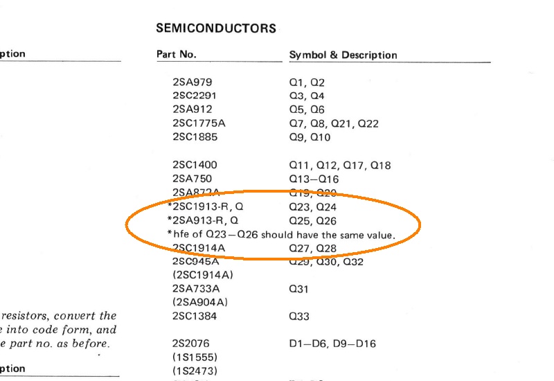 |
| Fig.33, according to the service manual, we have to buy some transistors, measure them, and find the pair with the most similar hfe |
Let's look at a selection of driver transistors. We'll have to accept a few mV of DC offset, or buy 20 pairs!
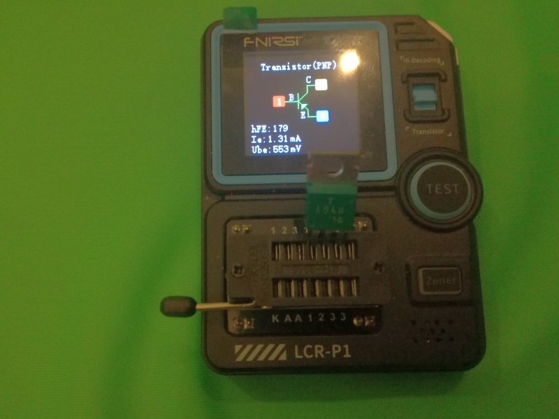 |
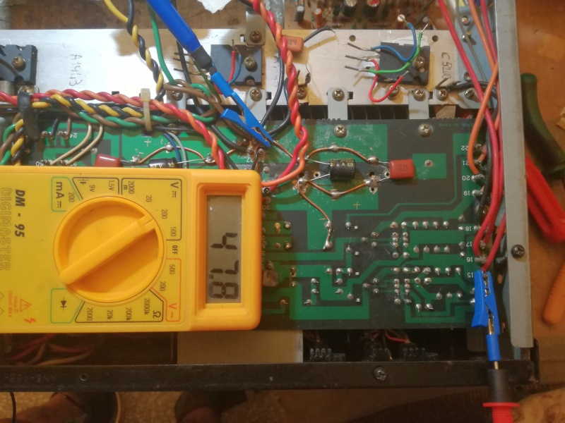
| Fig.34, yes, it is a genuine green 2SA940, vintage, from one of the two suppliers. Meter with updated firmware and self-calibrated before measurement |
The hfe value may not be accurate, but we need a comparison between the pair (however, we measure the same transistor by disconnecting it, turning off the meter, turning it back on, and reconnecting the transistor. We do this at least three times, writing down the values, i.e., short-term reproducibility).
With the instrument, we measured ALL the transistors in the amplifier section of the two channels, both the old ones, removing them one by one, and the new ones.
We measured ALL the diodes and also the Zener diodes. Regarding the Zener diodes, it should be noted that in the previous repair attempt, a 30V Zener diode was installed instead of a 13V one (but what the heck are datasheets for?).
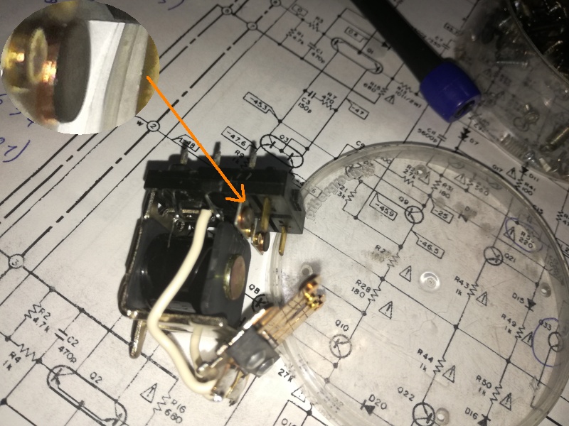 |
| Fig.35, after 35 years of service, the original relay has badly oxidised contacts. If the coil is in good condition, do NOT replace it, but clean the contacts |
To clean it, DO NOT use sandpaper of any kind, not even 1200 or 3000 grit, as this will damage the surface, making it rough, and after a month it will really need to be thrown away.
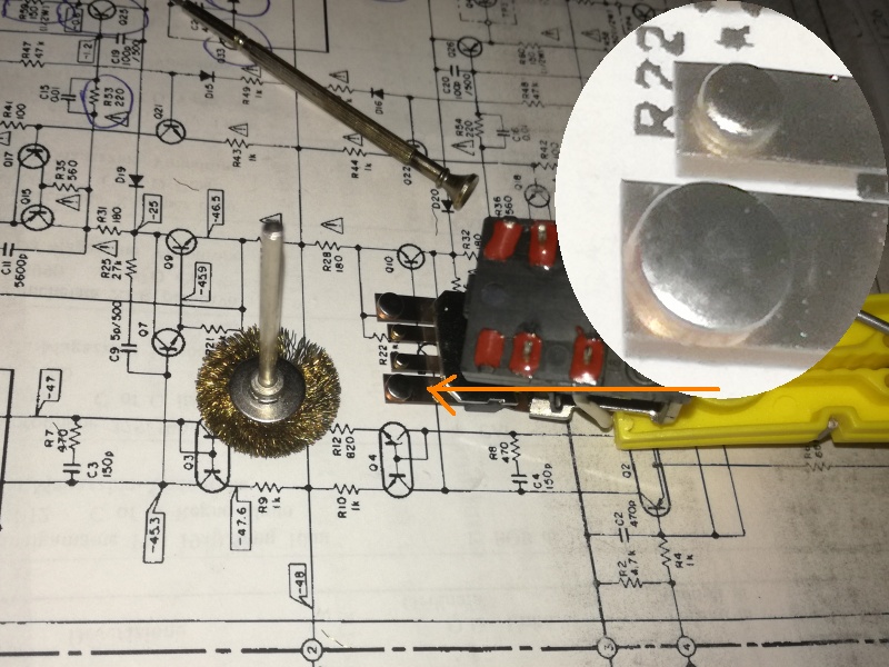 |
| Fig.36, we use a brush with brass strands and a Dremel running at low speed to thoroughly clean the contacts, leaving them smooth and shiny. Unfortunately, if there had been any platinum or gold plating, it has certainly disappeared by now |
We note that the contacts are thick copper discs, not some new €2 relay.
Having already tested the power supply stage on its own, a VI tracing device (similar to the Hameg HZ65-3 or the famous Octopus, certainly not a Tektronix TR210) is used to check the final stage at various points on the two channels for comparison.
A more complete, variable frequency version was presented as a kit in Elektor magazine (testeur de composants, Elektor n.211, 1996), and on another page you can see a modern version made by me. You have no idea how many faults can be found with such an instrument.
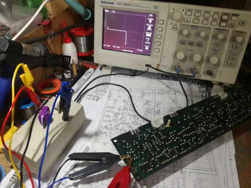 |
| Fig.37, on the left, our Octopus with selectors for three voltages and three currents, in the centre, the clips on the base-emitter of the 2SA940, at the top, the I-V signal on the oscilloscope |
Getting a nice XY curve on a DSO is not easy, you have to work on the settings, low-pass filters, and triggers. With an old 10MHz analogue tube oscilloscope, it's easy.
|
| Fig.38, IV curve tracers are useful for testing assembled components, such as D1, D3, and Q1, all together. After a few months of use, you will understand how a group like the one shown here should show |
Help can be found in an article by George R. Steber in Circuit Cellar in 2019, Create Your Own IV Curve Tracer, which shows how to visualise many other electronic components, available in download.
Once all the steps in the previous paragraph have been successfully completed, we can install the board shown in fig. 38, solder all the wire wraps, and we are ready to switch it on for the first time.
As usual, you will need either a Variac or the famous series of bulbs, everyone has their own method.
Follow the instructions in the service manual, set all potentiometers to zero, and switch on the amplifier. Measure the voltages on the test points, at the various points indicated in the schematics.
If everything is OK, proceed, but since there are many new components, leave it on for at least 2 hours before setting.
 |
| Fig.39, finally, we set the bias, first to 53 mV, leave it on for another hour and then set it to 66 mV |
The bias setting at 66 mV is delicate, the amplifier responds very slowly to the rotation of the potentiometer, so patience is required.
In order to achieve reliable operation, correct certain defects found in almost all amplifiers, and update the circuitry, here are some modifications and updates, whether intentional or not.
Let's start with the replacements necessary to bring the amplifier back to life, then we'll look at the modifications.
| . | original | subtitute | why |
| C29-C30 | 220μF/80V | 330μF/100V | better filtering |
| C39-C40-C41-C42 | 8000μF/50V | 10000μF/63V | better filtering |
| TP1-TP4 | 2SC2525 | 2SC5200 | impossible to find original, most current |
| TP2-TP3 | 2SA1076 | 2SA1943 | impossible to find original, most current |
| Q27-Q28 | 2SC1914A | 2SC2240 | impossible to find original, already fitted by Pioneer |
| Q23-Q24 | 2SC1913 | 2SC2073 | unable to find original, same characteristics |
| Q25-Q26 | 2SA913 | 2SA940 | unable to find original, same characteristics |
| D21-D22-D24 | 1S2472 | BAV20 | unable to find original, same characteristics |
| D25 | MZ-130 | 13V 1/2W | same value of zener, but new |
With these replacements, the amplifier works. We can proceed with the modifications.
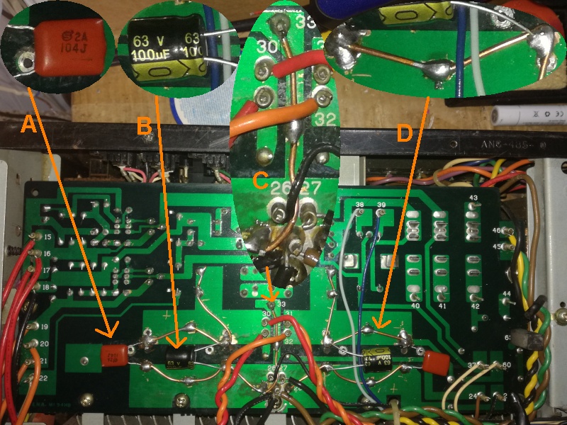 |
| Fig.39, modifications to the power supply stage: A) bypass of 0.1μF, B) bypass of 100μF, C) 1mm solid core to obtain more current for ground, D) 1mm solid core to fit the snap-in and obtain more current |
With 20000μF as the filter value, a bypass of approximately 1/100 of the value is required. Due to space constraints, we use B) as shown in the photo. Today, a capacitor such as A) is always used for power supply bypass.
I discuss the problem of PCBs (in amplifiers, speakers, power supplies, etc.) that are poorly designed to withstand high currents on every page of my website. Here, we add a 1 mm solid wire of pure copper, see C) and D).
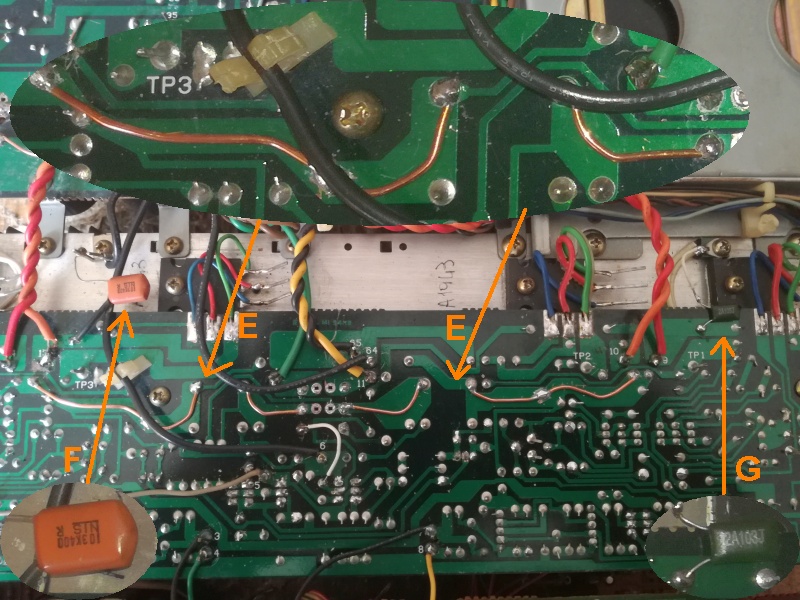 |
| Fig.40, modifications to the amplifier stage: E) use a 1 mm solid core to obtain more current from the transistor to the speaker, F) it is strange that only one supply bypass was originally fitted on the negative side, G) add a 0.01μF/100 V bypass on the positive supply |
Some manufacturers are aware of the problem with PCB traces that cannot handle the current, so they add thicker wires to solve the problem; here is an example.
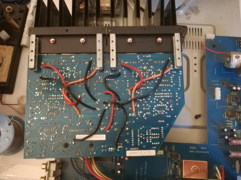 |
| Fig.41, Cambridge Audio, Azur 640A integrated amplifier, 60W, lets take a look at the entire amplifier section and the thick cables fitted by the manufacturer |
After switching on, we notice that the power indicator light is also broken. It is a small bulb with very long wires that connect to pins 37 and 60.
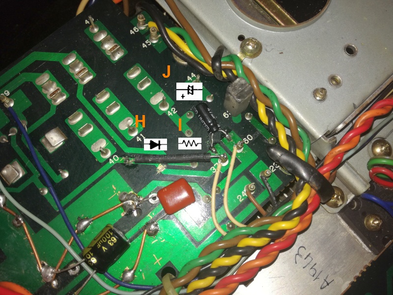 |
| Fig.42, there is little space, so we install a 3mm green LED in place of the bulb and make the following modifications: H) 1N4002 diode, I) 510 ohm 1/2W, J) 47μF 16V |
We just need to solve the problem in fig. 5, cutting off the head of the rest of the screw, which is rusted and stuck in the frame.
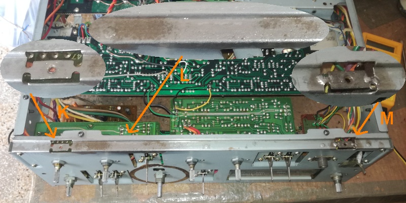 |
| Fig.43, first of all, using a Dremel, protective eyewear and a face mask, and a steel wire brush, we cleaned the edge of the frame and the back, obtaining L). After applying some Svitol, it was easy to remove the screw using a pair of pliers K). For M), however, I had to cut the frame, use an ultrasonic bath with a phosphoric acid solution, remove the screw and solder the cut piece back onto the frame |
Fig. 43 is emblematic of a repair that a repairman, who had to support his family with his work, would have solved with two new holes in the frame and two self-tapping screws. I can spend time on it and find solutions, even considering that this amplifier had been deemed junk.
I forgot to ask the owner about it earlier, but the display's frame couldn't stay like that.
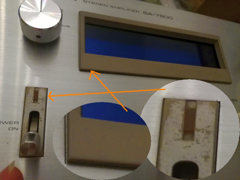 |
| Fig.44, first, make a cardboard template cut precisely to fit the frame and secure it with tape; then, using 400-grit and then 1200-grit sandpaper, remove the faux chrome finish to expose the plastic |
The front panel is scratched, the knobs are scratched too, and the edges are damaged, but nothing can be done about it; some of the lettering has already worn away (on the potentiometer) and attempting a thorough clean would remove it all.
I don't want to characterise the amplifier as the most famous magazines do, but let's measure some fundamental parameters just to see if it works.
As you know, I have my doubts about the output transistors, the 2SA1943 / 2SC5200 series, originally from Toshiba, which is used today in many amplifiers, but the pair is so famous that there are endless fakes around.
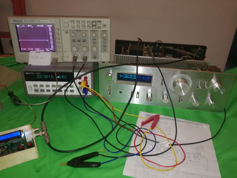 |
| Fig.45, the other set of instruments is working, so we set up a temporary set just for the Pioneer. As soon as we switch it on, we see the display working with a small signal, which is excellent news |
The fluorescent display still needs to be calibrated. Let's proceed.
 |
| Fig.46, the service manual tells us how to calibrate the display for 10W on 8 ohms using two small trimmers on the display PCB. For all measurements, we use the AUX input and measure 225V after the variac |
The calibration shown in Fig. 46 is another step towards operation. Now leave the amplifier on with a square wave producing 2.83V on 8 ohms, i.e. 1W, for at least 1 hour. Do not think that this is an easy task; some amplifiers fail with this treatment.
Let's test the amplifier's clipping on 16 ohms, 8 ohms and 4 ohms with both channels in operation, and also measure the current consumption.
 |
| Fig.47, let's display both channels, with a 10x probe, and move the traces to see the clipping better (of course, my analogue HAMEG cathode ray tube shows very thin traces, is this progress?) |
Let's move on to the other measurement, this time on a single resistor. Above, there were two in series.
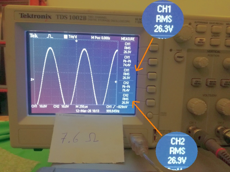 |
| Fig.48, always using probe 10x, always with channel 2 level slightly higher, always with potentiometer at maximum |
Better than expected result, let's see how it performs on 4 ohms
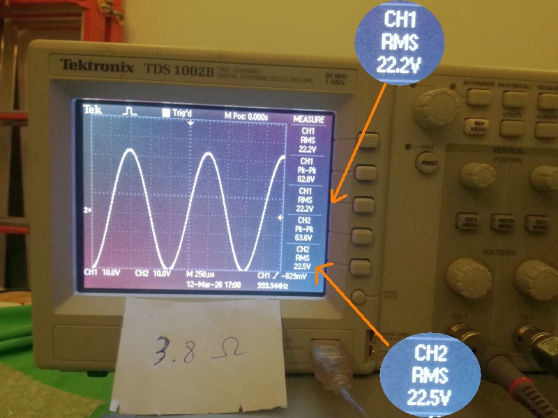 |
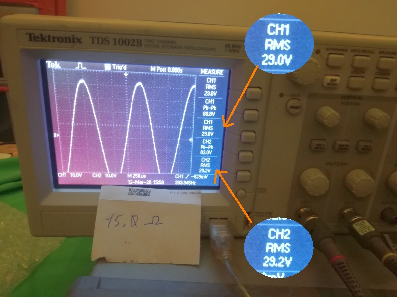
| Fig.49, once again, channel 2 is higher, but the voltage value is surprising, and the load is below 4 ohms |
We calculate the power, output current, consumption and efficiency by reading the values in the last three photos.
| load (ohm) | output (volt) | output (watt) | output (ampere) | supply (ampere) | supply (watt) | efficiency (%) |
| 15 | 29 | 56.06 | 1.93 | 0.8 | 180 | 62.29 |
| 7.6 | 26.3 | 91.01 | 3.46 | 1.4 | 315 | 57.78 |
| 3.8 | 22.2 | 129.69 | 5.84 | 2.3 | 517.5 | 50.12 |
Bear in mind that to take a decent photo, you need to take 3 or 4, and in the meantime, the amplifier is working at 101% power. If it has survived, then perhaps we have done an excellent job.
As expected, the efficiency and electricity consumption figures are slightly low for a true Class AB rating. This suggests that the device operates in Class A for part of the time.
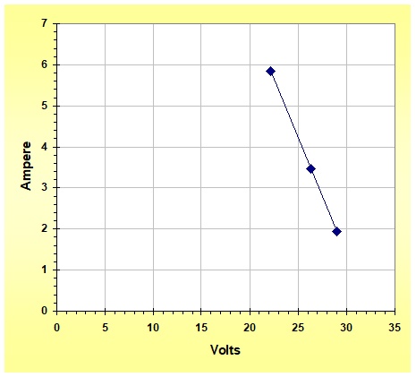 |
| Fig.50, the curve of the Limit Load Characteristic is incredibly good for such an old amplifier. It's easy to see why this Pioneer is still so highly rated by audiophiles |
One more measure to go, but this time we'll automate it!
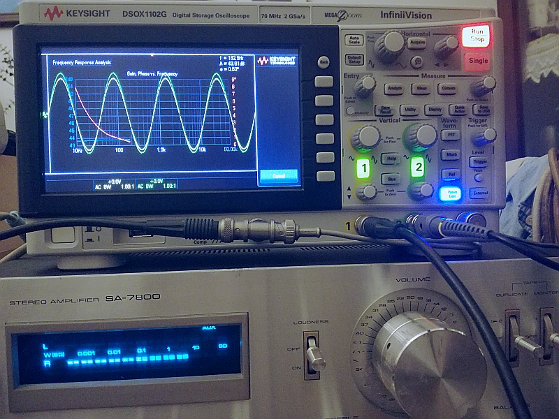 |
| Fig.51, after reading many pages of the manual and completing numerous settings, here is the "automatic" frequency response measurement. The photo shows the scratches on the volume knob |
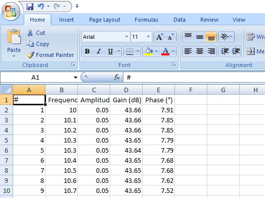
Lets wait for the measurement at 1000 points and we get.
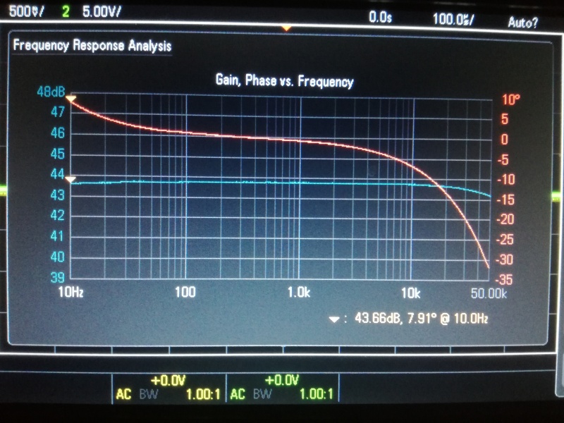 |
| Fig.52, AUX input, volume control at maximum, 8-ohm purely resistive load. Note the scale of just 1dB and the phase scale of just 5 degrees, but we took the measurement at around 5W, not 1W as is normally done! |
Less than half a dB loss at 50 kHz - the amplifiers quality is confirmed: an excellent purchase (now that its been repaired and modified).
 |
| Fig.53, Perhaps someone would like to take a closer look at this graph, you can find it in the download |
Searching the internet for reviews of the SA-7800, you can also find someone who, in order to repair it, changed all the capacitors, all the resistors and I don't know what else, and then complained about the sound it produced.
Apart from the fact that a collector would want everything to be original, or if repaired, at least as we have done here, trying to use original components, it is worth repeating once again.
The sound of a HiFi system is created by the whole. For this Pioneer, the whole consists of over 500 components, not just the C35, and the whole is like an orchestra where you cannot replace 30% of the instruments and expect to improve it.
Lets see what weve got:
We have an excellent amplifier at this stage. The only thing missing is a preamp/power amp split, which is feasible but not wanted by the owner.
The amp can now compete with modern gadgets costing three times as much.
In addition to all the original component datasheets, you will need the service manuals and addenda, which can be found below, but that's not all.
| In the last years at Universita' Degli Studi di Roma La Sapienza |
Dr. G. Visco already contract professor for Chemistry in Environment & Cultural Heritage into ---------> |
Laurea Degree Course of Sciences Applied to Cultural Heritage for Diagnostic and for Conservation |