| read the discalimer | speaker history | substitute ? | measure before | repair it |
| measure after | what cables | download files | . | . |
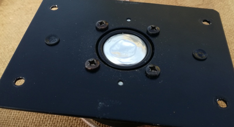 |
| Fig.1, the Elac 25DT-31 tweeter with its pressed dome, which is so deep that it touches the bottom of the back, resonance chamber |
All trademarks mentioned and links are presented here for informational purposes only and to confirm statements made by the author. The author of these pages DOES NOT receive any remuneration from the mentioned brands and the listed links.
In any case if you decide to use the suggestions on this page you do so at your own risk. Repairing electronic equipments, even just opening it, can put your life at risk, so don't do it.
If you do not accept and/or not understand the statements in this disclaimer, written in blue, exit this page immediately.
Everything exposed in this web page is only a suggestion, probably you won't obtain the aim from you prefixed following it.
A true collector is looking for a) original items without any replaced parts, b) or if a Critical Restoration has been done that it is possible to go back to the original version. Lacking the previous 2 statements the object (not only for me) has a value of zero euros.
Be very careful when buying a vintage, antique or historic loudspeaker. After 40 or 50 years, the magnets suffer from demagnetisation and the neoprene suspensions are now a wooden ring, the plissé and impregnated silk has opened up in the folds, and the foam, now sticky like bitumen, will drive the repairer crazy.
And the worst is yet to come: oversized broken coils, oval or square suspensions that are impossible to find, cardboard cones with impossible angles. And there is no cure for everything.
Beautiful speakers, with captivating sound when new, but a proper restoration can cost much more than the car itself, as in the case of this Fiat 500B.
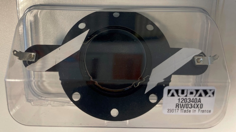
Not much information is available about this driver, but it has been used in many British-made speakers in at least two variants: one shown in the photo and one with cut corners.
Some models have a built-in metal grille, while this one has an external grille. However, it seems that the external grille was not useful (or more likely, it was removed by someone with a keen-ear because it sounded bad!).
Some models have a plastic mounting plate with "TDL Electronics" stamped on it, others have an aluminum plate with a funnel-shaped or recessed hole. In short, little is known about TDL's tweeter use among so many similar models.
As always, I strongly advise against replacing the tweeter, even if the coil is broken. However, forums and blogs are full of suggestions for possible replacements. Without offering any advice, let's look at some 120x90 mm alternatives:
Obviously, I don't have all these tweeters at my disposal, but I found photos and information on the Internet (thank you), and some audiophiles might be interested in this list.
We have a wonderful opportunity to see if a tweeter with a badly squashed aluminum dome changes in frequency response and impedance, or if nothing changes and it can be left "squashed".
But what are we measuring? We are NOT characterizing a driver with all possible T&S parameters, not even power handling and impulse response. I think the following are sufficient:
| side | DCR (ohm) |
Resistance at 1KHz (ohm) |
Inductance (uH) |
Resonance from curve (Hz) |
Resonance from curve (ohm) |
| Right before |
5.94 | 7.71. | 77.3 | 1363.3 | 8.0 |
| Right after |
5.96 | 7.66 | 77.9 | 1384.2 | 7.93 |
| Left before |
6.09 | 8.33 | 25.7 | 1471.1 | 8.82 |
| Left after |
6.11 | 8.44 | 25.2 | 1437.9 | 8.91 |
| Audax TW025A1-12x9 |
5.8 | 8.52 | 13.0 | 1449.7 | 9.12 |
Clearly, the table above was compiled at the end of the restoration process. There is a significant difference in inductance between L and R, so the impedance curves will also differ. This difference is also evident in the resonance.
We read the Audax TW025A1-12x9 datasheet to compile the table. It is the most similar to our TDL, but, as usual, the numerical values and curves in the datasheet do not match. The famous Elac-TDL tweeter table is ridiculous, with all resonances between 650 and 750 Hz.
First, we measured the impedance curve of the two tweeters using the LX.1746 impedance meter and Ulrich Müller's software.
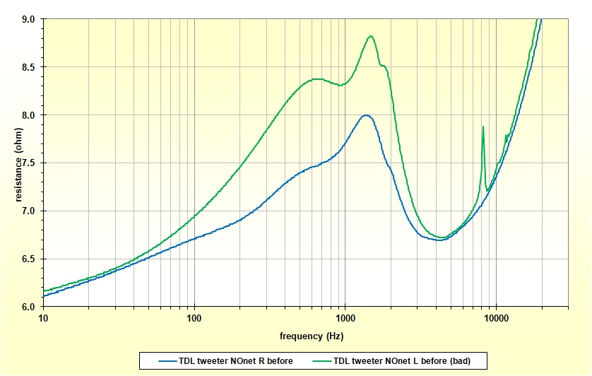 |
| Fig.2, shows the impedance curves of the two TWs. As can be seen, the left TW shows a very different trend, with an unsightly peak at around 8 kHz due to the dome collapsing |
We also measure the frequency response of the two tweeters in quasi near-field.
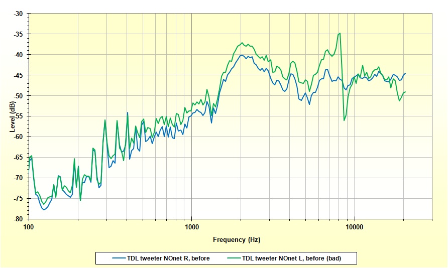 |
| Fig.3, frequency response (photo) of the two TWs in quasi near-field, here, if possible, it is even worse, with the impedance peak at 8kHz having a severe impact on the frequency response |
We have understood that a tweeter with a collapsed dome MUST BE REPAIRED, I repeat, NOT replaced but repaired. It may not be perfect again, but it will certainly be listenable.
The same applies to a dome midrange, even more so given that vocals, piano and acoustic guitar all fall within the midrange frequency range.
There is no single method for repairing a tweeter like the one shown in Fig. 1. Depending on the type of material and the type of damage, I can think of at least four methods that can be used. Each method has its own advantages and disadvantages, so let's look at them one by one.
Pulling tape
Although it seems easy, it requires some manual dexterity. You need to choose the right adhesive tape: one that is easy to stick on, has a strong grip on the dome, and does not leave any glue behind. 3M Tape 1350T-1 transformer tape is a good option.
Small strips of tape are usually used, but to make them stick, you mustn't cause any further damage or crush the dome even more.
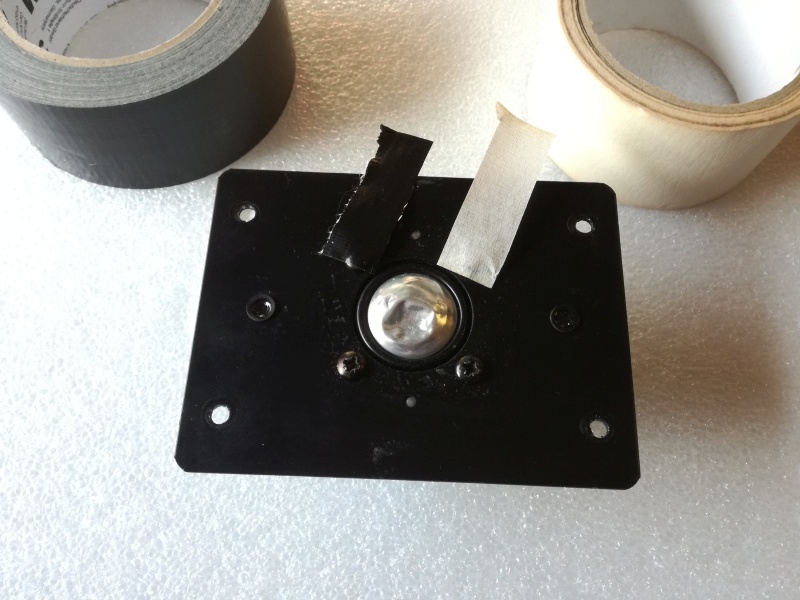 |
| Fig.4, example of two different adhesive tapes used to extract a collapsed dome, but not for this type of dome! |
The method works well on silk or fabric domes, i.e. on soft materials, but not on plastic, cardboard or aluminium.
An alternative is to glue a strip of string to the centre of the damage with Vinavil and pull it after 24 hours. This often works, but then you need to clean off the glue with a scalpel and a steady hand. The use of Blu-Tack or similar products is not recommended, as they do not adhere well enough.
Vacuum
Here, audiophiles indulge in even bizarre ideas to use some kind of "vacuum" (for a 15-inch woofer, I used a Dyson V15 to straighten the dust cover). The method involves a vacuum pump, a suitable flexible tube, and a suction nozzle made of some soft material.
The suction nozzle must be chosen with a diameter suitable for the dome: in some cases, it is as large as the dome itself, or small enough to be centred only on the damaged part. In any case, it must adhere well and maintain the vacuum in order to be effective.
Should the pump be switched on first? Is it enough to simply bring the nozzle close to the surface, or should it be pressed firmly against it? How long should you wait? These are just some of the questions you should ask yourself. Since tweeters are expensive and/or hard to find, and since it's easy to cause even worse damage, it's better to carry out lots of tests using a dome made of the same material on a pair of tweeters bought at a flea market for euro 10.
 |
| Fig.5, An example would be a diaphragm vacuum pump, a rubber (Caoutchouc) vacuum tube whose softness would allow it to be used as a nozzle. But even in this case, the method is not suitable for this dome |
The vacuum method works on cardboard domes, even on woofer domes, provided that the amount of vacuum and suction flow are correctly adjusted. It works well on silk or fabric domes, and even some thin plastic domes can be repaired in this way.
Push from behind
This is the most effective method for straightening a flattened dome. In fact, it's the only method for aluminum, titanium, or hard plastic domes. The lighter, thinner, and harder the dome, the more difficult it will be to completely smooth out the crease.
Plastic domes can be slightly heated with a hair dryer once detached to better smooth out the creases, but this requires skill.
 |
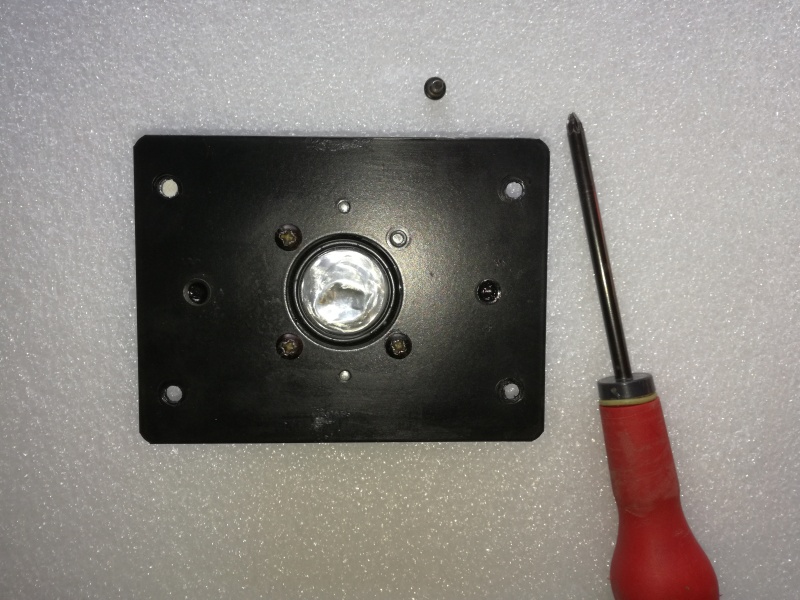
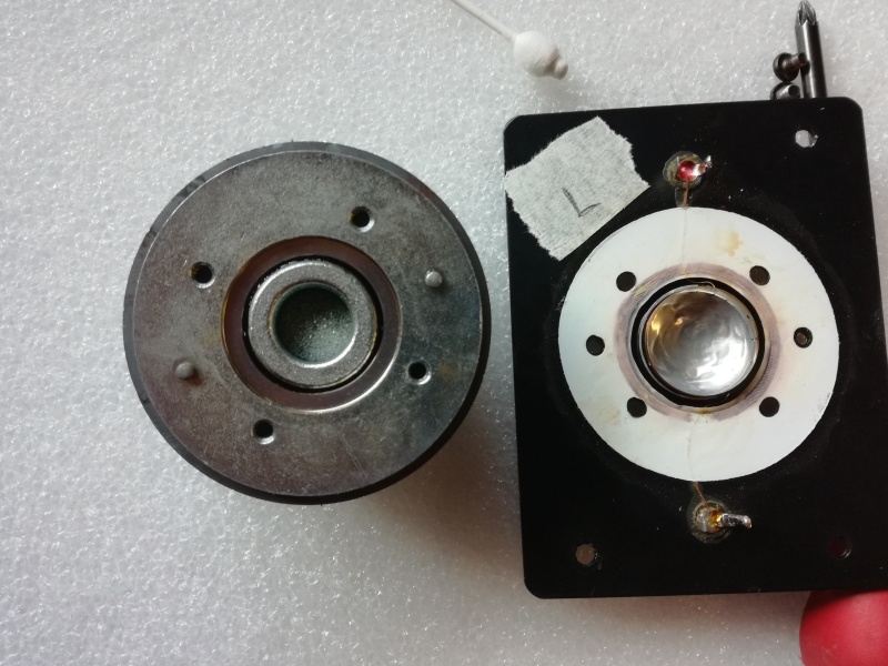
| Fig.6, Knowing how this tweeter is made, first mark the position of the magnet relative to the coil. A 180-degree reversal will throw the coil off center, or perhaps it will get jammed in place |
Now we have to remove the faceplate from the magnet. At least 50% of tweeters are made like this, but there are many variations. Good luck! Even worse, some are glued, and in that case it is often impossible to save the coil and dome.
 |
| Fig.7, Pozidriv, Phillips, Supadriv, JIS B1012, Frearson, Reed&Prince, there are many types of Phillips heads, and it is essential to use the right screwdriver. You also need a steady hand and a little strength because sometimes these screws have a threadlocker to prevent them from coming loose due to vibrations |
Once the screws have been unscrewed, a delicate step follows. Sometimes there is double-sided adhesive tape to hold the faceplate in place, or years of use have stuck it to the magnet.
For this type of tweeter, the coil and contacts must be detached from the magnet, leaving them on the faceplate. We will then look at a different case.
 |
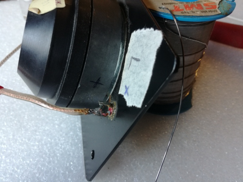
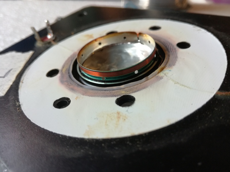
| Fig.8, And here is what the dismantled tweeter looks like. The dome is glued from underneath to the faceplate, the coil wires are long and insulated with lacquer up to the contacts, and a paper ring dampens vibrations towards the magnet. At the top center is an extremely expensive tool used to flatten the dome |
Those who say that tweeters don't have a rear chamber are idiots. All tweeters (and almost all midrange speakers) are small pneumatic suspension chambers. Here you can clearly see the chamber, in fact, some have sponge, wool, or similar materials inside the chamber! Heil, AMT, and electrostatic tweeters aside.
Now we have to place the dome face down, perhaps inside a roll of adhesive tape that is a little tall, and try to straighten the folds. The rigid material will still remain marked.
Do not try to smooth out the grooves, as you will create new ones. The more rigid it is, the more likely it is that the dome will crack if you insist.
 |
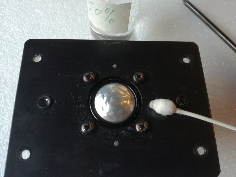
| Fig.9, Using the very expensive tool (the ones for children), here is the result. We need to talk about the oil that can be seen on the coil |
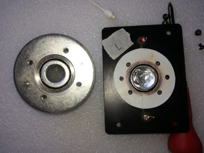
We are lucky, the manufacturer has placed two pins in the magnet that will help us reassemble the faceplate (but many TWs don't have them).
 |
| Fig.10, Looking closely at the coil, we can see traces of oil. This is ferrofluid, as described by TDL. While working on the dome, you must NOT touch the coil so as not to remove this oil |
Returning to ferrofluid, the guy with the famous barn owl ears or long-eared owl ears, if he gets this far, will remove it!
Apart from the fact that it has now entered the coil windings, so they pretend to remove it, this type of oil loaded with soft iron nanoparticles helps to focus the field on the coil and also to cool it (since 1973 in AR, Epicure, Showco).
If it has dried and become sticky, you can try (but with no guarantee of not causing damage) to remove it with the tool already seen in fig. 8, lightly soaked in isopropyl alcohol, in several passes, then leave it to dry for a few hours. Finally, using a very fine brush, coat the coil with a very thin layer of ferrofluid, but only the coil, not the coil former or the magnet (I have seen some know-it-alls on the Internet pouring oil into the air gap and some people following their advice).
Be wary of fake audiophiles and self-proclaimed experts who only give you certainties. When I have to do a job like this, my heart races and I'm almost certain I'll do some damage. Never follow the blunt advice of big-mouthed loudmouths.
 |
| Fig.11, The suspension of this dome is made of rubber, too small to perform measurements as with woofers, but after 30 years, a quick wipe with the same solution as in fig. 20 on the woofers page may help |
Will straightening the dome without attempting to remove the damage but trying to rebuild the volume of the rear chamber work?
4th method, substitute
The last method is to replace the voice coil and dome, which is also effective for burnt coils or other similar damage.
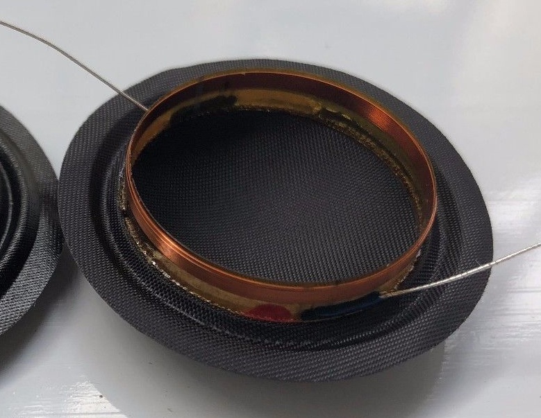 |
| Fig.12, an Audax coil, note the similarity with fig. 10. The coil must be glued on the back of the faceplate, these wires must be insulated, and the dome is different here, made of impregnated silk |
The difficult part is centring the coil in the tiny space of the air gap. There are at least three methods, but this page is already too long and, luckily, we may have saved the original coil.
 |
| Fig.13, if we are a little luckier, the TW has a plate with a coil, dome and centring device, as shown in the picture. Just solder the files and follow the assembly instructions |
There is actually a fifth method, but it is not recommended: make a hole in the dome and use a hook to try to straighten the deformation. Perhaps this only works for cardboard domes, but it is easy to cause more damage than with the previous methods.
In conclusion, there may be other methods that are not codified, but this list should be sufficient to repair a crushed dome.
We must repeat the measurements taken before the intervention. We are not interested in the absolute value of dB, efficiency or polar response, but accuracy in the results is necessary for comparison. The most difficult point is the near-field repositioning for the frequency response (1 feet).
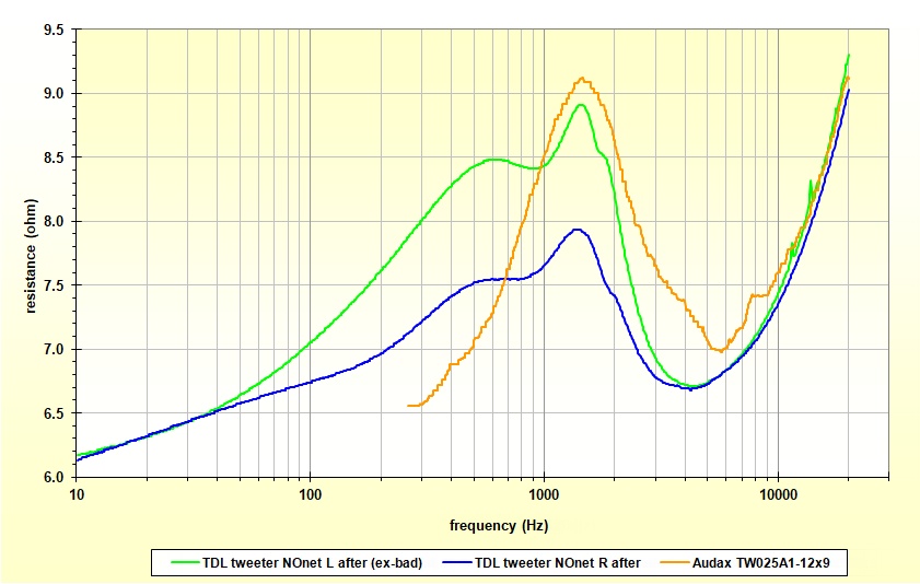 |
| Fig.14, looking at the green curve, we have an excellent result. Unfortunately, we cannot make two tweeters that are slightly different from each other identical, but we have nevertheless superimposed the resonance with those in the Audax datasheet |
Let's compare the two impedances of the left TW before and after.
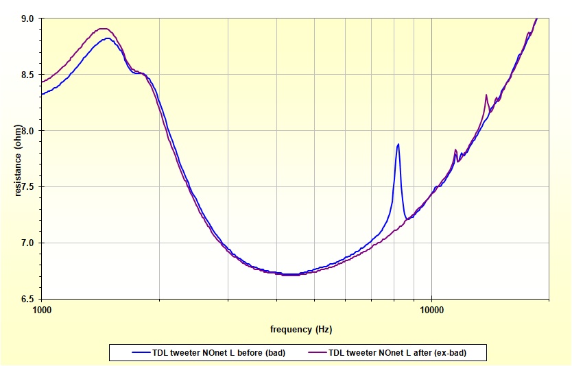 |
| Fig.15, we changed colours to highlight the before and after. The resonance peak at around 8kHz has disappeared, but the defects in the dome are now visible at 13.7kHz, much smaller. The resonance at approximately 11.4 kHz present on both tweeters is interesting, perhaps caused by the rear chamber |
I suspect that few audiophiles are interested in the impedance curves of their tweeters, perhaps they are more interested in the curves that follow.
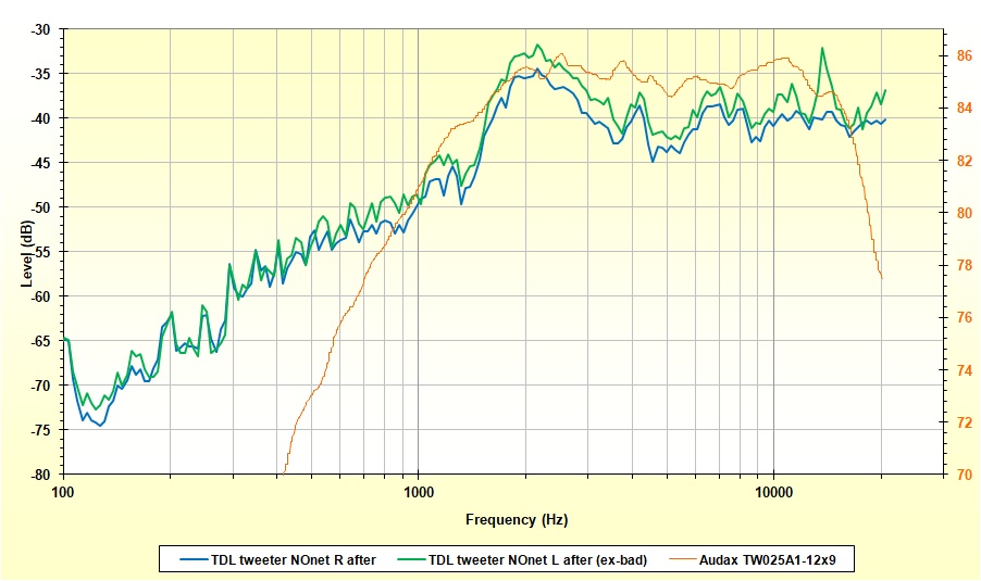 |
| Fig.16, should we congratulate those who did the work? The frequency response is almost overlapping, the left channel remains more efficient, and we have already seen the peak at over 13 kHz in the impedance, but now it is in an area where there is a few music |
Finished! But with these restorations, you always need a bit of luck. Years ago, a similar tweeter could not be dismantled as shown in fig. 8, and the coil was torn.
The cable section inside all the TDLs I have seen is sufficient, and the copper quality is good. However, we often like to give our toys a coat of paint just for the sake of doing something.
Without opening up the hell of "cable sound", using a 99.999% copper (5N) cable, perhaps drawn in a nitrogen environment (OFC), so that some copper atoms do not oxidize during processing, and then immediately incorporated into resin, might slightly improve our loudspeaker.
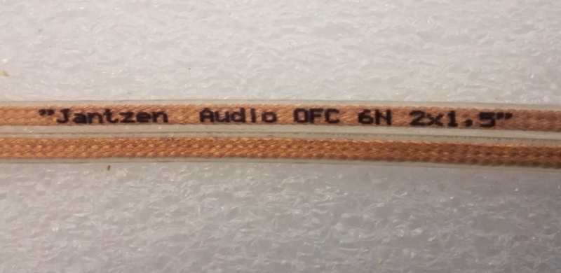 |
| Fig.17, The reader should thank his friend Jacek for this suggestion regarding the internal cables in the speaker. Here is a very soft, truly flexible cable (unlike my QED cables) that should not add resonance or damage the contacts. Furthermore, it is reasonably priced and has excellent specifications |
The cross-section is more than sufficient for any driver I know of. To the critics: read the section on the L1 wire, the largest one, with a diameter of 1.7mm and a cross-section of 2.3mm2, but we are talking about at least 30 metres of wire on the positive pole, and I remind you of the disaster on this crossover PCB or the thin tracks on the Monitor/RSTL PCB.
Below are the files mentioned on this page and available for download:
| In the last years at Universita' Degli Studi di Roma La Sapienza |
Dr. G. Visco already contract professor for Chemistry in Environment & Cultural Heritage into ---------> |
Laurea Degree Course of Sciences Applied to Cultural Heritage for Diagnostic and for Conservation |