| read the Discalimer | the Copper | a typical speaker cable | what measures are being taken | what cables do we use |
| capacitance, measurement | measuring resistance | measuring inductance | impedance and its measure | a comparison |
| which one to buy? | the deaf one | the guru and jogi | suggested reading | . |
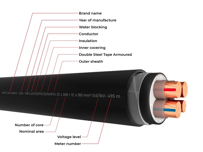 |
| Fig.1, What information should be printed on an electrical cable, whether for 230V or low-voltage use, from Ngoc Lan Cable. Perhaps it is illegal to sell electrical cables of any kind without the clear markings shown above (and at €2,000 per metre, it's criminal) |
All trademarks mentioned and links are presented here for informational purposes only and to confirm statements made by the author. The author of these pages DOES NOT receive any remuneration from the mentioned brands and the listed links.
In any case if you decide to use the suggestions on this page you do so at your own risk. Repairing electronic equipments, even just opening it, can put your life at risk, so don't do it.
If you do not accept and/or not understand the statements in this disclaimer, written in blue, exit this page immediately.
Everything exposed in this web page is only a suggestion, probably you won't obtain the aim from you prefixed following it.
A true collector is looking for a) original items without any replaced parts, b) or if a Critical Restoration has been done that it is possible to go back to the original version. Lacking the previous 2 statements the object (not only for me) has a value of zero euros.
Copper conductors keep "the world" connected, from the power plants to our washing machines, from the alkaline battery in a razor to its motor, from the lithium battery pack to the motors in drills and electric cars.
Given the immense importance of copper conductors, it is easy to understand why there are so many standards governing them (and their insulation).
The fact that, to a very minor extent, the audio industry also uses insulated electrical conductors has no bearing on the copper industry.
After all, there are people who pay €1,000 per metre, or even €5,000 (for something that costs €3 to produce industrially), and they don't even ask for ISO, CEN, IACS, BSI, LME, JIS or ASTM certification.
How many standards are there regarding copper conductors and purity?
I'M SORRY FOR THIS LONG INTRODUCTION, but there are so many rules to read and follow, yet none of the so-called experts (charlatan, quack, cult leader, snake oil salesman) mention them, someone has to do it!
Standards relating to the purity of copper specify the minimum copper content and the permissible levels of non-metallic impurities (such as carbon, oxygen or phosphorus) for various industrial applications.
Other standards define the total of other elements (other than copper) as the sum of Ag, As, Bi, Cd, Co, Cr, Fe, Mn, Ni, O, P, Pb, S, Sb, Se, Si, Sn, Te and Zn, or for the specified individual element.
First and foremost, a conductor for the electrical and electronics industry must comply with the standards for "Electrical Conductivity" measured against the International Annealed Copper Standard (IACS). Pure copper should be greater than or equal to 100% IACS.
Furthermore, the various purity standards must be met, with measurements carried out in accordance with specific analytical methods to determine the composition of the alloy (copper and ...).
Each continent has subsequently developed standards for all the necessary measures:
A cable is a component designed to carry a signal with as little distortion as possible.
A cable cannot 'improve' the sound in a creative sense, but a poor-quality cable can degrade it through excessive resistance, capacitance or inductance, or electrical reflections.
A poorly matched cable carrying 1 kW to the antenna will destroy the amplifier within half an hour.
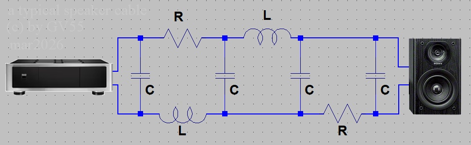 |
| Fig.2, We will then discuss these components - R, L and C - one by one, as they are found in any cable connecting an amplifier to speakers, but EVERY cable contains all of them |
In fig.2 the components are shown as individual parts, but within the cable they are 'distributed' - that is to say, every centimetre contains them all, as does every millimetre and every metre.
What does the philosopher and logician Bertrand Russell have to do with speaker cables? Or, more precisely, what does he have to do with the market for high-fidelity audio accessories, or even worse, audiophile accessories? Perhaps because his famous quote applies to this group of savvy businesspeople: "Some things are believed because people feel as if they must be true, and in such cases an immense weight of evidence is necessary to dispel the belief", from the book The Impact of Science on Society, 1952.
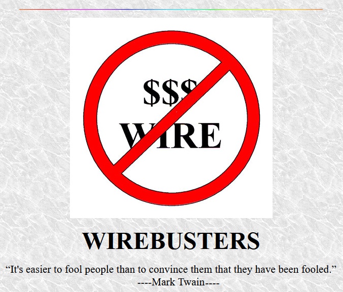 |
| Fig.3, from the web page of Roger Russell, a MUST READ description of speaker cable, with a famous phrase (attributed to Mark Twain) |
"The glory which is built upon a lie soon becomes a most unpleasant incumbrance .... How easy it is to make people believe a lie, and how hard it is to undo that work again!" (Mark Twain, autobiographical dictation, 2 Dec 1906, in Autobiography of Mark Twain, Vol2, California University Press, 2013)
Russell's marvellous page, which explains how a speaker cable works and debunks a few myths, deserves at least a mention:
Despite the effectiveness of Gordon's cable demonstration and the truth about speaker wire, people visiting the McIntosh room at the shows, who had not experienced the cable demonstration, were disturbed that we were using ordinary heavy zip cord instead of one of the popular brands of speaker wire. Instead of listening to the McIntosh speakers and electronics, they recalled "bad" things they had been told about "common" speaker wire and this promoted questions about the "inferior" wire being used. When we changed the wire to a popular brand of wire, customers were happy with the setup, and directed their attention to the McIntosh equipment. (at half of web page).
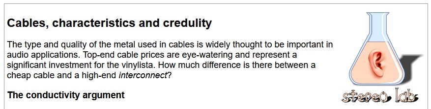 |
| Fig.4, from the web page of Pspatial Audio, another website that debunks the myths about speaker cables |
True audiophiles will be familiar with both Cox Electronics and Miranda Technologies, where Richard Brice worked. He was the designer of Phædrus Audio's preamplifiers and microphones, as well as the software designer behind Stereo Lab software and the renowned Francinstien stereo enhancement system.
Let's take a close look at his page on audio cables, which debunks a few myths. But permit a citation:
High-frequency effects. Lastly, the marketeers of analogue audio cables - when they are not obsessing wth conductor purity - often invoke descriptions of physical effects relating to the propagation of high-frequency signals in cables. The importance of high propagation velocity and the minimisation of skin effect are particular favourites. The problem here is the confusion of the requirements for cables for digital audio signals and those for analogue audio signals. The subjects of transmission lines and skin effect and how they relate to digital and analogue audio signals are covered in the panel.
Why audio speaker cables are so expensive?
The AI reply (Gemini):
Please read this fascinating response provided by an aggregator of four AI models.
To carry out all measurements, at least the following two requirements must be met:
This applies to all measurements, but even more so to the measurement of inductance.
We always measure at least one pair of adjacent wires and all the combinations 1-2 and 3-4-5-6 described in the next paragraph.
Resistance
As Roger Russell tells us, the first thing to measure in a speaker cable is its resistance. Values of less than 1 ohm are expected, so a high-quality instrument and some "experience" are required for the measurement.
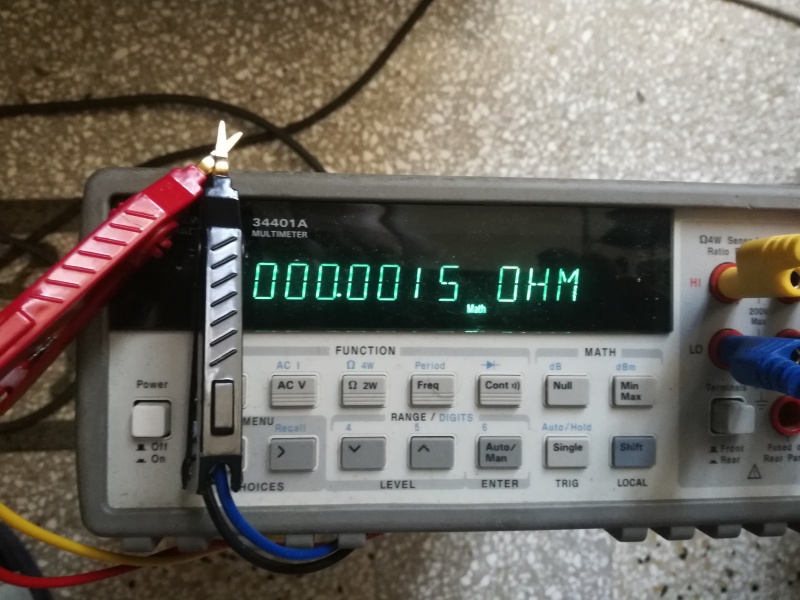 |
| Fig.5, using an Agilent 34401A, Kelvin probes and the 4-wire measurement method, it is possible to measure resistances down to 1.5 milliohms |
Capacitance
In previous discussions, the cable's capacitance has been mentioned, this is also an important parameter to measure, but it must be done accurately.
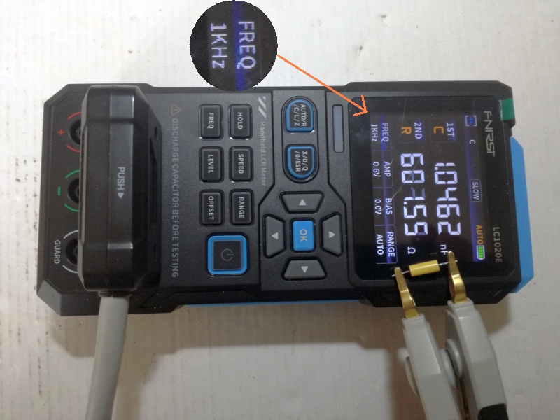 |
| Fig.6, 1.0 nF, 1%, polyester, Icel capacitor measured using an Fnirsi LC1020E with Kelvin clips. Let's take a look at the measurement frequency, which is variable |
Inductance
It's rarely mentioned in discussions about speaker cables (and even less so when it comes to signal cables), but as we'll see, there's a significant difference between one cable and another.
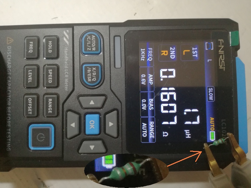 |
| Fig.7, brown, grey, gold, silver, 1.8 µH, 10%, filter inductor for oscillator |
Impedance
The impedance of the cable (i.e. all the components shown in Fig.2) should not alter the speaker's impedance, as shown in the figure.
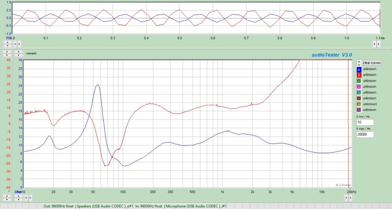 |
| Fig.8, Measurement of the impedance of a real loudspeaker with cabinet in free-field. Note the resonance at 18 Hz of the tuning port, the Rmax of 24.2ohm and Rmin of 5ohm |
Lenght
The two cables are different lengths - about 1 metre apart - but all measurements should be converted to a standard length so they can be compared.
Furthermore, if we convert all the measurements to a length of 10 metres, other audiophiles might be able to replicate them for their own cables and make a comparison.
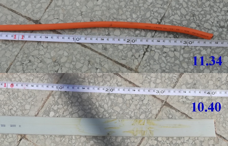 |
| Fig.9, here are the lengths of the two cables: 11.34m and 10.40m. With mouse-over you can see how the R-L-C measurements should be taken |
A simple calculation is all it takes to convert 2.560 ohms on 11.34 m to 0.2257 ohms on 1 m
After a few discussions with a friend - a true enthusiast but rightly sceptical about the now sky-high prices of cables - I decided to suggest two industrial cables used by electricians and installers for specialised applications.
With just two conductors, there is no choice, but with 4, 6 or 12 wires, the choice of link geometry is crucial. Each geometry has its own unique characteristics designed to address the fundamental issues associated with speaker cables, with the aim of improving audio performance.
There is no single "best" geometry, but rather the one which, given the number of conductors, minimises all the problems.
We have chosen a cable cross-section between 5 and 6 mm², which is more than sufficient for the required 5-metre distance.
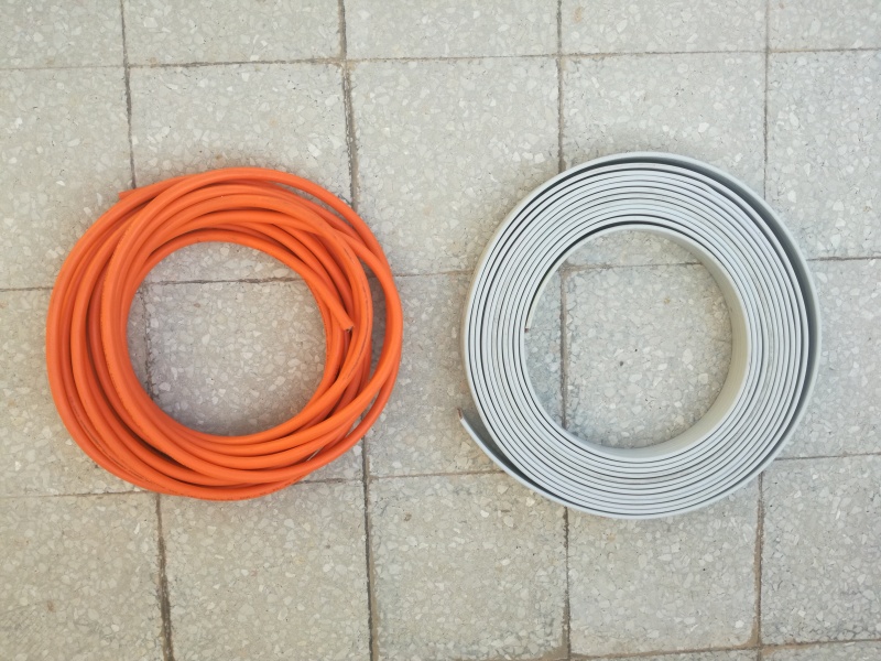 |
| Fig.10, on the left 11 meter of FFROR 4x 2.5mm cable and on the right 10 meter of H05VVH6-F cable |
Class 6 cable
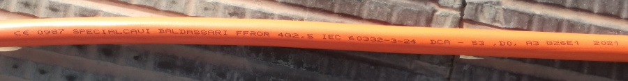 |
| Fig.11, ultraflex industrial cable: CE 0987 Specialcavi Baldassarri FFROR 4G2.5 IEC 60332-3-24 DCA S3 D0 A3 G26E1 2021. Here a photo of the coil of cable |
An ultra-flexible cable (IEC 60228 Class 6) with a cross-section of 4 x 2.5 mm², used in industrial applications. Note the numerous certifications printed on the cable.
We will discuss prices in the conclusions. It is being phased out of production because the 900 V insulation is expensive; the specifications are listed below.
FFROR Orange, flexible bare copper class 6 CEI 20-29 conductor, PVC insulation, TI2 quality, PVC sheath TM2 quality.
Nominal voltage Uo/U:300/500V, Test voltage:2000V, Maximum operating temperature:+70°C, Minimum operating temperature:-10°C.
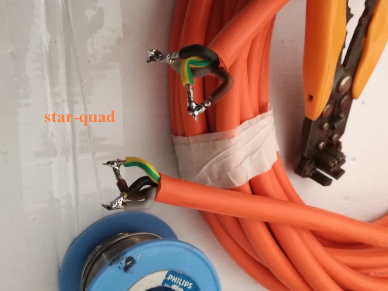 |
| Fig.12, There are only two ways to connect the four wires of the cable, shown here is the cross-pairing method |
Here are two ways to connect a quad-wire cable and create a speaker cable (probably different cable, different colors!):
Never, ever use a quad-wire cable for a bi-wiring system. Space between bass and treble conductors is 1mm apart. For bi-wiring, you need two cables that run to the amplifier, ideally using the amplifier's Speaker A and Speaker B outputs.
Class 5 cable
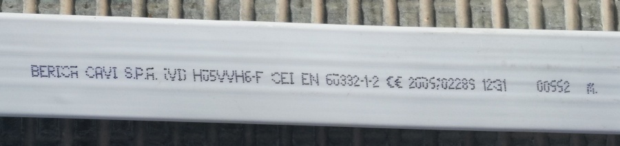 |
| Fig.13, Flexible cable: Berica Cavi spa CVD H05VVH6-F CEI EN-600332-1-2 CE 2005/02289 12G1 0100 |
A flexible cable (IEC 60228 Class 5) with a cross-section of 12 x 1.0 mm². You can see him peering out from beneath the lift cabins, used other industrial applications. Note the numerous certifications printed on the cable, more then prevoius.
H05VVH6-F flat gray RAL7035, flexible bare copper class 5, PVC insulation, TI2 quality, PVC sheath TM2 quality.
Nominal voltage Uo/U:300/500V, Test voltage:2000V, Maximum operating temperature:+40°C, Minimum operating temperature:0°C, Curvature radius: thickness × 10, Unsupported free span: < 35 m.
There are many ways to connect 12 wires together to create two speaker terminals. Let's look at just the most interesting ones:
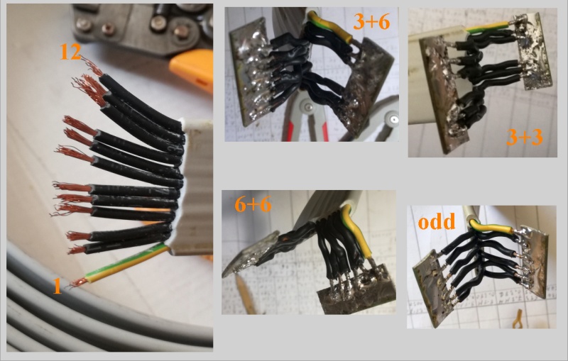 |
| Fig.14, pairing the 12 wires of flat cable, the 4 methods was described below. To connect the wires, we use a copper plate and 60/40 tin. Here you can find the high resolution image |
Over the years, we have seen similar cables, including some well-known ones, such as the Tmr-Audio Ramses, Cambridge Audio Linea 8.4, Acoustic Research MicroFlat, Nordost SuperFlatline and Straight Wire.
Never, ever use a similar cable for a bi-wiring system. Space between bass and treble conductors is too tight For bi-wiring, you need two cables that run to the amplifier, ideally using the amplifier's Speaker A and Speaker B outputs.
Of course with Star-Quad and Parallel configurations, we get a 5 mm2 cable (~ AWG10). With Odd, 3+3, 6+6 and 3+6 configurations, we get a 6 mm2 cable (~ AWG9).
I almost forgot: on many circuits, 3//4 indicates that wires 3 and 4 are soldered together, as a parallel.
Capacitance measurement with the cable laid out, connected at one end to the tester and left open at the other end. The same type of connections made at one end must be repeated at the other end of the cable, see, for example, Fig.12.
As already said, we measure the entire 10 metres of the cable, laid out, and recalculate for 1 metre.
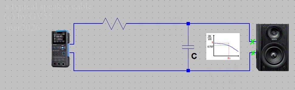 |
| Fig.15, let's assume a cable with only capacitance. However the presence of even a small series resistance produces a low-pass filter! The cable must be disconnected at their end to ensure an accurate measurement |
The primary parameter is capacitance in pF, the secondary parameter is ESR in ohm.
| cable 1 metre | 100Hz | 1000Hz | 10KHz | 100KHz | ||||
| FFROR 4x2.5 | C (pF) | R (ohm) | C (pF) | R (ohm) | C (pF) | R (ohm) | C (pF) | R (ohm) |
| green vs black * | 129 | 42680 | 122 | 5273.3 | 103 | 692.2 | 101 | 17.72 |
| green vs brown * | 130 | 41975 | 123 | 5300.7 | 108 | 721.3 | 104 | 18.43 |
| star-quad ## | 340 | 13315 | 335 | 1851.8 | 300 | 202.8 | 280 | 23.28 |
| parallel # | 199 | 25485 | 185 | 3262.8 | 176 | 442.7 | 166 | 21.07 |
| H05VVH6-F 12x1 | C (pF) | R (ohm) | C (pF) | R (ohm) | C (pF) | R (ohm) | C (pF) | R (ohm) |
| 3 vs 4 ** | 43 | 1.25M | 88 | 10769.2 | 79 | 1115.3 | 71 | 40.29 |
| 4 vs 5 * | 64 | 2.5M | 73 | 13365.3 | 65 | 1480.7 | 56 | 51.20 |
| odd | 775 | 8942.3 | 7150 | 1326.9 | 638 | 111.6 | 573 | 7.02 |
| 3+3 ## | 289 | 26730 | 272 | 3317.3 | 243 | 296.1 | 218 | 2.50 |
| 6+6 # | 115 | 25M | 108 | 8211.5 | 98 | 855.7 | 87 | 81.63 |
| 3+6 | 213 | 34615 | 201 | 4365.3 | 181 | 564.4 | 160 | 8.46 |
| notes | * adjacent wires, ** adjacent wires, but 3 is in the first cluster and 4 in the second cluster of three, # parallel and 6+6 configurations follow the same design logic, ## star-quad and 3+3 configurations have the same logical structure |
|||||||
Around 120 pF for the two adjacent wires of the FFROR and around 70 pF for the two adjacent wires of the flat cable are good values. The geometry used to connect these wires in parallel is also important.
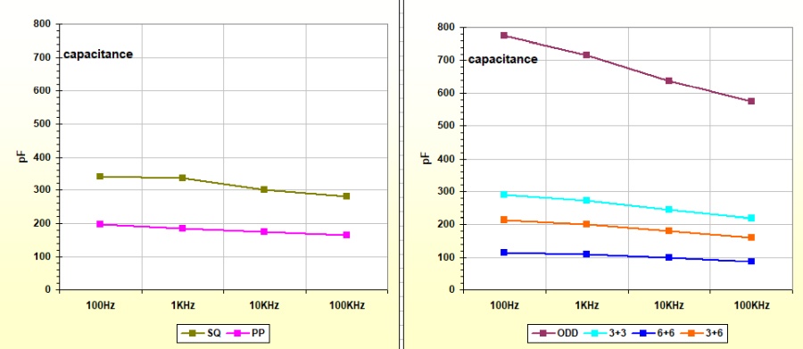 |
| Fig.16, By measuring the cable's capacitance as shown in Fig. 15, we obtain these graphs. For the FFROR, it appears that the PP geometry is the best. However, for the H05VVH6-F, the ODD geometry must be ruled out, as the capacitance is far too high (per metre!) |
A detailed analysis will be carried out later, but we can already rule out the Odd configuration (1//3//5//7//9//1 vs 2//4//6//8//10//12), which produces excessively high capacitance at all frequencies.
BEWARE of cables with 20, 24 or more wires, which, if incorrectly configured, could also produce capacitance levels that are dangerous for Class D, Class T, Class H, or overly simplified tube amplifiers.
At least when it comes to cable resistance, almost everyone agrees that it must be low - very low, in fact, compared to the speaker's impedance.
The same type of connections made at one end must be repeated at the other end of the cable, see, for example, Fig.14. As already mentioned, we measure the entire 10 metres of the cable, laid out, and recalculate for 1 metre.
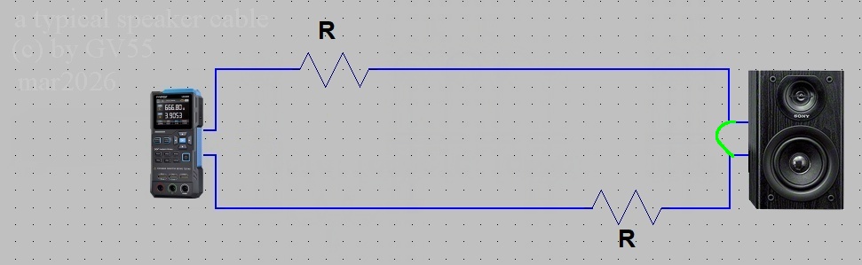 |
| Fig.17, with reference to Fig. 2, let us assume that the cable consists solely of resistors, one for each wire. For the measurement, the cable must be short-circuited at the end (green jumper) |
However, there are loudspeakers that exhibit as little as 2 ohms at certain frequencies, so the reference value becomes the minimum impedance value, see Fig. 8. This is also indicated in the table halfway down Roger Russell's page.
Critics - whether out of sheer prejudice or because they blindly follow the latest guru like sheep - will no doubt have already criticised and disparaged these cables, but they are still AWG10 and AWG9!
The primary parameter is Resistance in ohm, the secondary parameter is XR (reactance) in ohm.
| cable 1 metre | DC | 100Hz | 1000Hz | 10KHz | 100KHz | ||||
| FFROR 4x2.5 | R (ohm) | R (ohm) | X (ohm) | R (ohm) | X (ohm) | R (ohm) | X (ohm) | R (ohm) | X (ohm) |
| green vs black * | 0.0164 | 0.0154 | 0.0004 | 0.0154 | 0.0038 | 0.0170 | 0.0377 | 0.1384 | 0.3250 |
| green vs brown * | 0.0164 | 0.0153 | 0.0004 | 0.0152 | 0.0037 | 0.0169 | 0.0364 | 0.1425 | 0.3264 |
| star-quad ## | 0.0081 | 0.0075 | 0.0001 | 0.0075 | 0.0015 | 0.0081 | 0.0147 | 0.0220 | 0.1265 |
| parallel # | 0.0090 | 0.0075 | 0.0001 | 0.0075 | 0.0016 | 0.0082 | 0.0154 | 0.0227 | 0.1320 |
| H05VVH6-F 12x1 | R (ohm) | R (ohm) | X (ohm) | R (ohm) | X (ohm) | R (ohm) | X (ohm) | R (ohm) | X (ohm) |
| 3 vs 4 ** | 0.0403 | 0.0366 | 0.0004 | 0.0366 | 0.0041 | 0.0378 | 0.0411 | 0.1690 | 0.3441 |
| 4 vs 5 * | 0.0405 | 0.0366 | 0.0005 | 0.0366 | 0.0049 | 0.0380 | 0.0488 | 0.1966 | 0.4340 |
| odd | 0.0064 | 0.0059 | 0.0000 | 0.0059 | 0.0006 | 0.0058 | 0.0056 | 0.0212 | 0.0478 |
| 3+3 ## | 0.0064 | 0.0058 | 0.0001 | 0.0059 | 0.0015 | 0.0071 | 0.0128 | 0.0396 | 0.1108 |
| 6+6 # | 0.0063 | 0.0058 | 0.0003 | 0.0060 | 0.0034 | 0.0100 | 0.0283 | 0.0904 | 0.2394 |
| 3+6 | 0.0061 | 0.0058 | 0.0002 | 0.0059 | 0.0020 | 0.0082 | 0.0172 | 0.0521 | 0.1468 |
| notes | * adjacent wires, ** adjacent wires, but 3 is in the first cluster and 4 in the second cluster of three, # parallel and 6+6 configurations follow the same design logic, ## star-quad and 3+3 configurations have the same logical structure |
||||||||
Reactance: an ideal resistor has zero reactance (XR = 0 ohm). Reactance is exclusively the frequency-dependent opposition to alternating current (AC) caused by parasitic inductors and/or capacitors.
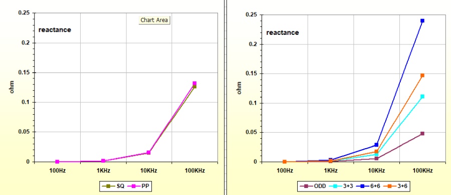 |
| Fig.18, if measured as shown in Fig. 17, reactance is a good indicator of the cable's quality. The graph on the left for the FFROR does not allow us to reach a conclusion, whereas on the right, for the H05VVH6-F, we can discard the 6+6 link and proceed to study the others |
At the end of the capacity tests, we had ruled out the ODD configuration (1//3//5//7//9//11 vs 2//4//6//8//10//12) and we are now ruling out the 6+6 configuration, where the first 6 are pitted against the second 6.
This is a scientific selection method used in the classification of objects (iterative ranking-and-selection), but those with "big ears" are unlikely to like it.
Speaker cables carry alternating current and therefore have a magnetic field constantly growing and collapsing around their conductors. This causes an electromotive force to be generated within the cable which opposes the flow of current. This effect is known as self inductance and will be greater the further apart the current carrying conductors are spaced in the speaker cable.
With a properly designed amplifier, adding large amounts of inductance in series can produce an audible high frequency loss and phase shift which both affects the fidelity of the sound you hear and the accuracy of the stereo soundstage, it is therefore vital to keep cable inductance as low as possible. Copy here from QED The Supremus Report, pag.5.
Another interesting webpage that discusses the issues surrounding parasitic inductance can be found on the website of Jiaxing Aoliheng Cable Co., Ltd but I won't go into how many IEC certifications they have listed on their site or how little a 10 AWG speaker cable costs.
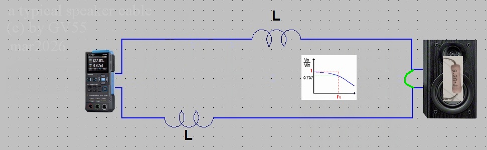 |
| Fig.19, still referring to Fig. 2, let us assume that the cable consists solely of inductors, one for each wire. For the measurement, the cable must be short-circuited at the end (green jumper). But .... when the cable is in use, the inductors form a low-pass filter with the internal resistance of the loudspeaker |
From fig.19, we can see that the low-pass filter depends not only on the cable's inductance but also on the speaker's impedance.
That is, it depends on the speaker's impedance curve, meaning that high inductance results in a cutoff frequency (phase shifts, impulse response, etc.) that varies continuously depending on the frequency reaching the speaker.
The primary parameter is Inductance in µH, the secondary parameter is R in ohm.
| cable 1 metre | 100Hz | 1000Hz | 10KHz | 100KHz | ||||
| FFROR 4x2.5 | L (µH) | R (ohm) | L (µH) | R (ohm) | L (µH) | R (ohm) | L (µH) | R (ohm) |
| green vs black * | 0.58 | 0.0154 | 0.60 | 0.0154 | 0.58 | 0.0170 | 0.52 | 0.1383 |
| green vs brown * | 0.57 | 0.0154 | 0.59 | 0.0157 | 0.57 | 0.0170 | 0.53 | 0.1392 |
| star-quad ## | 0.19 | 0.0075 | 0.24 | 0.0075 | 0.23 | 0.0081 | 0.20 | 0.0480 |
| parallel # | 0.34 | 0.0075 | 0.37 | 0.0075 | 0.36 | 0.0085 | 0.34 | 0.0774 |
| H05VVH6-F 12x1 | L (µH) | R (ohm) | L (µH) | R (ohm) | L (µH) | R (ohm) | L (µH) | R (ohm) |
| 3 vs 4 ** | 0.63 | 0.0366 | 0.66 | 0.0365 | 0.65 | 0.0378 | 0.58 | 0.1500 |
| 4 vs 5 * | 0.76 | 0.0366 | 0.78 | 0.0365 | 0.78 | 0.0380 | 0.69 | 0.1939 |
| odd | 0.08 | 0.0059 | 0.10 | 0.0059 | 0.09 | 0.0058 | 0.08 | 0.0261 |
| 3+3 ## | 0.22 | 0.0058 | 0.24 | 0.0059 | 0.20 | 0.0070 | 0.17 | 0.0410 |
| 6+6 # | 0.50 | 0.0060 | 0.52 | 0.0063 | 0.45 | 0.0100 | 0.38 | 0.0912 |
| 3+6 | 0.28 | 0.0059 | 0.32 | 0.0059 | 0.28 | 0.0081 | 0.23 | 0.0516 |
| notes | * adjacent wires, ** adjacent wires, but 3 is in the first cluster and 4 in the second cluster of three, # parallel and 6+6 configurations follow the same design logic, ## star-quad and 3+3 configurations have the same logical structure |
|||||||
In a conductor carrying alternating current, the inductance should ideally be zero. In real cases, however, the value usually increases as the frequency rises.
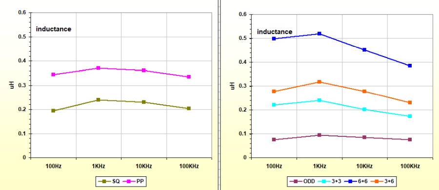 |
| Fig.20, when measured as shown in Fig. 19, inductance (which is overlooked by almost everyone) is one of the most important indicators of cable quality. The graph on the left for the FFROR shows the SQ coming out clearly on top, whilst on the right, for the H05VVH6-F, we see the 6+6 configuration once again coming off worst |
We already have the solution for the FFROR cable, Star-Quad cabling is superior in every respect. We have some doubts about the flat cable, as the reactance and inductance readings show ODD to be the best, whilst the capacitance readings show it to be the worst.
How important is measuring the impedance of a speaker cable? After taking the individual measurements of R, L and C, as we've seen previously, it might seem pointless, but there may well be some surprises in store.
At this stage, we've established that these two cables are excellent, we just need to decide on the geometry - or rather, not really, as we've already decided on the FFROR.
There are very few discussions online about speaker cable impedance, and the few that do exist are often deliberately misleading (Not for money ... but for cash).
The FFROR 4G2.5
 |
| Fig.21, to measure the cable impedance, it must be terminated with a resistor of a known value similar to the average impedance of a loudspeaker (as shown in Fig. 8) |
The resistor should be of the non-inductive and non-capacitive type. But setting aside the hot air spouted by charlatans and hucksters, up to 20 kHz almost all 1/4, 1/2 or 1W resistors are of this type.
Of course, you shouldn't choose a 10W wire-wound resistor, perhaps of the type wound on a ceramic tube!
 |
| Fig.22, by connecting the resistor shown in Fig. 21 directly to the measurement sockets of the LX1746 impedance meter and using the excellent software mentioned earlier, we obtain the reference curve - the zero value - against which to compare the cables. Here the high resolution |
We keep all the settings from Fig. 8 unchanged (96 kHz, etc.) and measure only the two combinations for the FFROR cable.
 |
| Fig.23, what a stroke of luck, there's something visible: a slight increase in impedance above 5 kHz compared to the reference curve. Here the high resolution |
It's not a stroke of luck, but a meticulous adjustment of levels and timing to highlight even the slightest difference, let's move on to the other geometry.
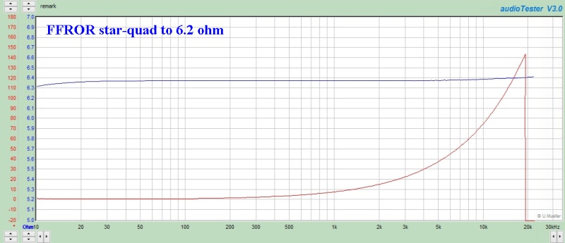 |
| Fig.24, impedance measurement for the Star-Quad geometry. Here the high resolution |
There is a noticeable difference above 5 kHz, with the Star-Quad configuration performing better, we will look at this in more detail in the comparison.
The H05VVH6-F 12G1
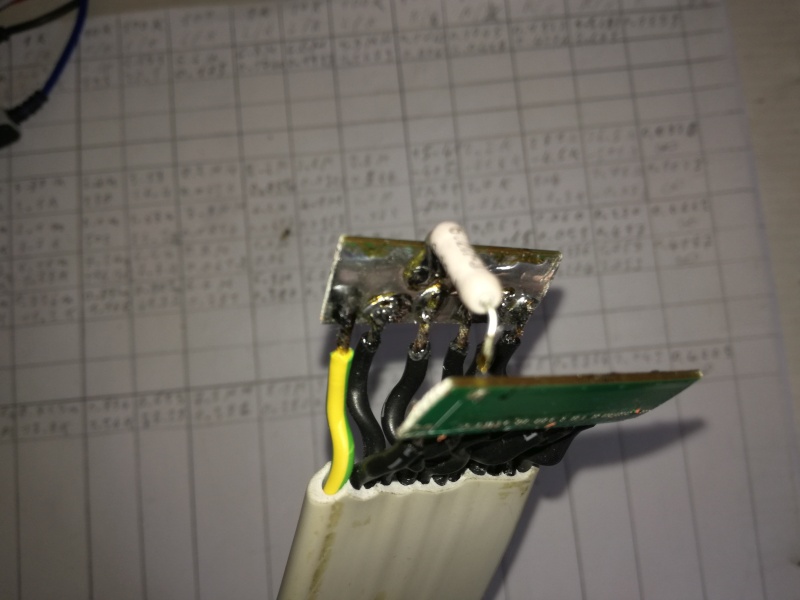 |
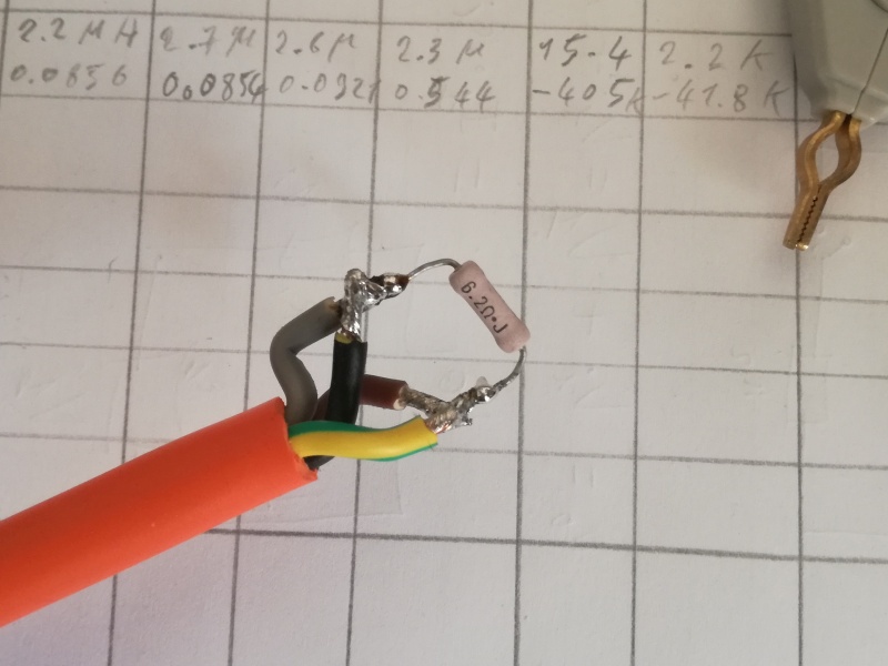
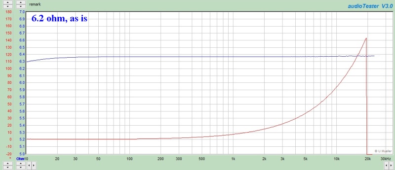
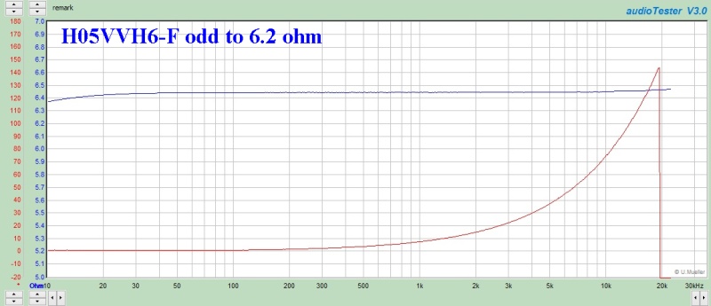
| Fig.25, We also use the same 6.2-ohm resistor as a terminator for the H05VVH6-F cable to simulate a loudspeaker (with incredibly linear impedance!) |
Even though it's a long and tedious process, let's see how the four geometry behave in terms of impedance.
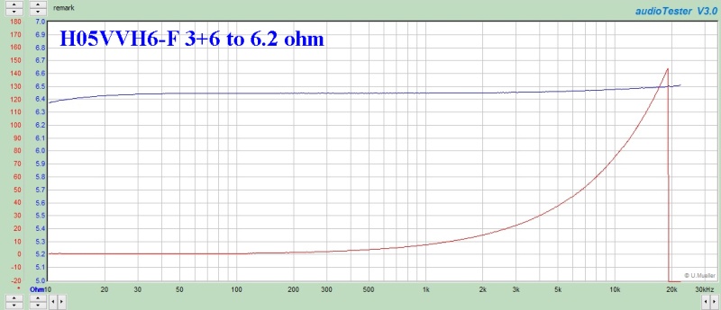 |
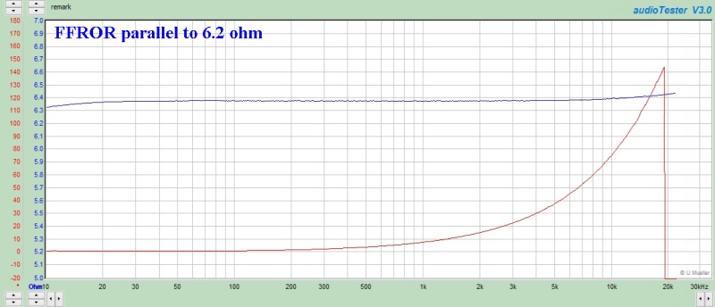
| Fig.26, impedance measurement for the 3+6 geometry. Here the high resolution |
As expected, there is a slight increase above 5 kHz; let's move on to the next configuration.
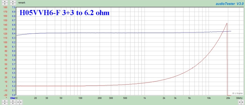 |
| Fig.27, impedance measurement for the 3+3 geometry. Here the high resolution |
Let's move on to the 6+6 configuration, which is the simplest but not the best.
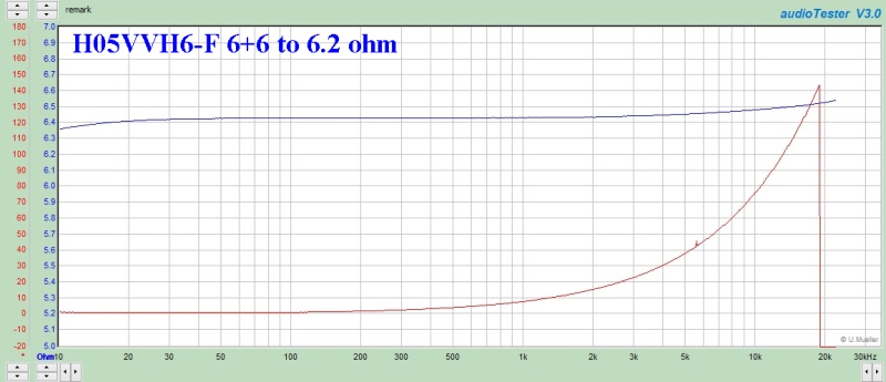 |
| Fig.28, impedance measurement for the 6+6 geometry. Here the high resolution |
And finally, the ODD configuration, where the wires are arranged in an alternating pattern.
 |
| Fig.29, impedance measurement for the ODD geometry. Here the high resolution |
To compare the results, we could plot the final sections of the curves on top of one another.
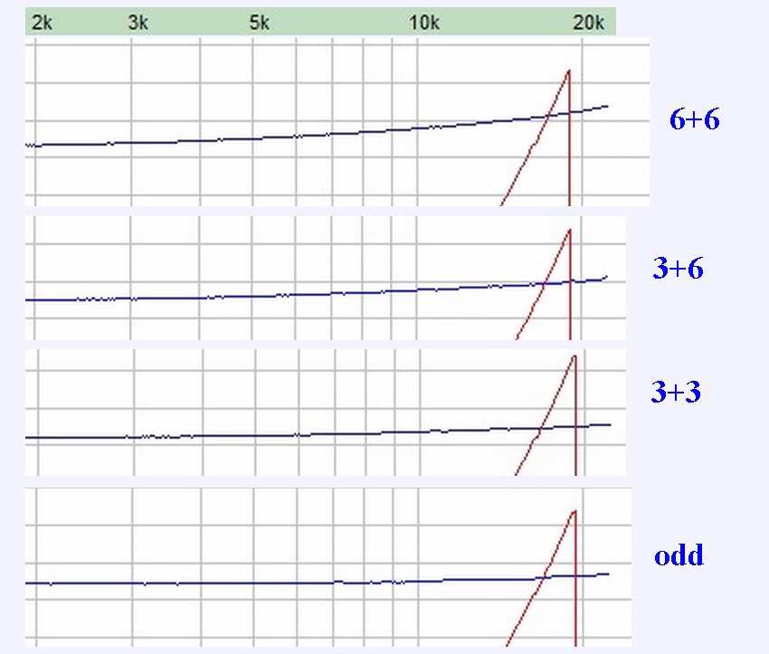 |
| Fig.30, with a bit of graphic design, some zooming in, and a bit of cutting and pasting, we can compare the impedances |
Once again, we're ruling out the 6+6 geometry. If we were to rank them from best to worst, we'd have: odd, then 3+3, then 3+6. But now we need to compare all the measurements.
Comparing cables is a global pastime, some people try to provide a scientific answer, even though manufacturers' biases - and their ignoble profits - skew the results.
Measuring capacitance, inductance and resistance, as well as secondary parameters (Q, X, ESR, etc.), is useful for classifying cables against one another.
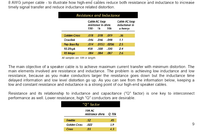 |
| Fig.31, a copy of page 9 of the paper Internationale Highend-Kabelhersteller und ihre technischen oder physikalischen Argumente für ihr jeweiliges Produkt-Design by Thomas-Michael Rudolph (TMR Elektronik, Berlin), which corresponds to our measurements |
Classification method:
| cable 1 metre | lower values are the best / rank | rank | ||||
| FFROR 4x2.5 | DC R (ohm) / rank | C (pF) / rank | XR (ohm) / rank | L (µH) / rank | imp (pixel) / rank | summa |
| green vs black * | 0.0164 | 101 | 0.3250 | 0.52 | n.a. | n.a. |
| green vs brown * | 0.0164 | 104 | 0.3264 | 0.53 | n.a. | n.a. |
| star-quad ## | 0.0081 / I | 280 / II | 0.1265 / I | 0.20 / I | 339 / I | 6 |
| parallel # | 0.0090 / II | 166 / I | 0.1320 / II | 0.34 / II | 344 / II | 9 |
| H05VVH6-F 12x1 | DC R (ohm) / rank | C (pF) | XR (ohm) | L (µH) | imp (pixel) | summa |
| 3 vs 4 ** | 0.0403 | 71 | 0.3441 | 0.58 | n.a. | n.a. |
| 4 vs 5 * | 0.0405 | 56 | 0.4340 | 0.69 | n.a. | n.a. |
| odd | 0.0064 / IV | 573 / IV | 0.0478 / I | 0.08 / I | 351 / II | 12 |
| 3+3 ## | 0.0064 / IV | 218 / III | 0.1108 / II | 0.17 / II | 348 / I | 12 |
| 6+6 # | 0.0063 / II | 87 / I | 0.2394 / IV | 0.38 / IV | 365 / IV | 15 |
| 3+6 | 0.0061 / I | 160 / II | 0.1468 / III | 0.23 / III | 360 / III | 12 |
Let's look at the right-hand column of Table 4. For the FFROR cable, the only choice of geometry is Star-Quad.
For the flat cable, however, there is one definite exclusion: the 6+6 geometry (which is the transposition of the Parallel).
For the other geometries, we are on a par, but remember that:
# the ODD has the highest capacitance,
# the 3+3 is the one that often comes second in the overall measurements (Fig. 18, Fig. 20, Fig. 30).
If 5mm2 is sufficient for you - that is AWG10 - the FFROR 4G2.5 is an excellent cable: easy to solder in a Star-Quad configuration, extremely flexible and offering excellent electrical performance.
It has one major drawback: it costs around €4 per metre. An alternative is the ÖLFLEX® SERVO FD 796 CP series, also Class 6, but it is only produced up to AWG1! It too has the drawback of costing €10 per metre for a 4G6.
The H05VVH6-F 12x1 cable is also an excellent choice, it gives us 6mm2, or AWG 9, and is very easy to run even under carpets. Furthermore, an enthusiast could try out the various configurations - first the 3+3, but also the 3+6 and the ODD - and work out (I was about to write "listen to", blimey, read below) which works best for their Amplifier-Speaker combination. Same drawback as the previous ones: 4 euros per metre.
If we could find the manufacturer, we could ask them to make one with a sheath without any markings, we're not interested in the certifications. Then we'd brand it "XyZxHx cable" and sell it for 5,000 euros for metre - that would make it magnificent.
I'm sorry, but someone's got to tell you: how old are you, 40? YOU'RE DEAF! Go on, get angry and swear at me, but it's in our genes.
A colleague anthropologist at university explained to me that when we came down from the trees and chose to walk upright (Homo erectus) around 2 million years ago in Africa, and then migrated to Asia and Europe, bringing with us the use of fire, our society of small organised groups and camps had over a million years in the Palaeolithic era to adapt our physiology.
Hearing was essential for young hunters to protect themselves from ambushes from behind and to locate sounds ahead on the X-Y plane, but it was no longer necessary for an elderly man devoted to sharpening a amygdala around the fire (maximum lifespan 45-50 years).
Organised human civilisation, defined by cities, writing and complex agriculture, is around 5,500-6,000 years old, with the earliest forms appearing in Mesopotamia (the Sumerians) around 4000-3500 BC. However, the first permanent settlements date back further, to around 9000-7000 BC at sites such as Jericho.
Too few years to alter the genetics of our ears, knees and spine.
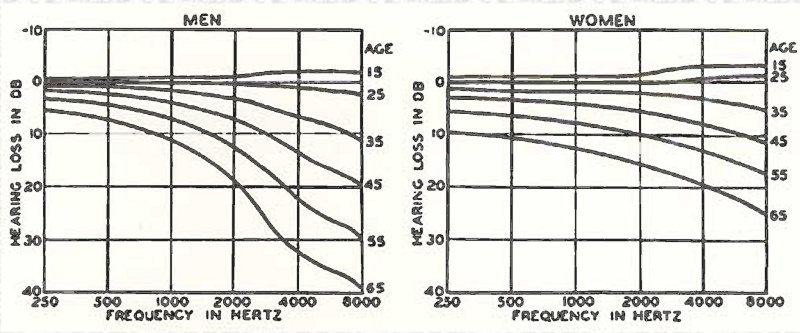 |
| Fig.32, However, as we age, our sensitivity to high frequencies decreases dramatically. The chart is from "Modern Sound Reproduction" by Harry F. Olson (978-0442262808). It shows the average hearing loss Vs age for men and women at frequencies from 250 Hz to 8000 Hz. This means that for a man at age 35, sensitivity is down about 11 dB at 8000 Hz. For a woman at that age, sensitivity is down only about 5 dB. Here you can find the high resolution image |
Please note the scale: 10 dB per division! We can infer that sensitivity is down a whole lot more at 20kHz. More in other web page of Rogerr Russell.
But is that person who goes on and on about a half-decibel in Camille Saint-Saëns' Violin Concerto No. 3 in B minor, Op. 61, specifically the final note of the first movement, a B7 (Si7), Superman?
NO, they're just people who make a living that way (see gurus below). They too have mortgages to pay, children to support, and so on. The same goes for the prestigious magazines that discuss cables, their suspension systems, their burn-in and directionality: they can't afford to lose their spellbound readers and advertising revenue.
Why are you so fed up with these so-called gurus?
Becouse a friend of mine, who isn't exactly rolling in money, has a Music Server with two 2TB hard drives full of digital music in a RAID-configured NAS. Some guru convinced him that he needed to spend over €500 + €500 for two audiophile SATA cables for inside the NAS.
Damn scammers and damn corporate shill magazines!
In a negative sense, a "guru" is someone who poses as a spiritual guide, sage or expert with special powers in order to manipulate people's good faith and gain personal advantages, usually financial or related to power, or even simply to achieve fame and visibility that they would never attain in their actual profession.
The main characteristics of this figure are as follows:
I suggest:
| In the last years at Universita' Degli Studi di Roma La Sapienza |
Dr. G. Visco already contract professor for Chemistry in Environment & Cultural Heritage into --> |
Corso di Laurea in: Scienze Applicate ai Beni Culturali ed alla Diagnostica per la loro Conservazione |