| main disclaimer | speaker disclaimer | Xover history | false, mistaken, fake, invented, and often malicious schematics |
what circuit |
| the problem | measure chokes | and then repair | or modify/upgrade | build the biwiring |
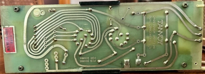 |
| Fig.1, Tannoy crossover for HDP 385a, PCB D35885, untouched, very good condition, for an auction on Internet (thanks). Here the high-resolution photo |
All trademarks mentioned and links are presented here for informational purposes only and to confirm statements made by the author. The author of these pages DOES NOT receive any remuneration from the mentioned brands and the listed links.
In any case if you decide to use the suggestions on this page you do so at your own risk. Repairing electronic equipments, even just opening it, can put your life at risk, so don't do it.
If you do not accept and/or not understand the statements in this disclaimer, written in blue, exit this page immediately.
Everything exposed in this web page is only a suggestion, probably you won't obtain the aim from you prefixed following it.
A true collector is looking for a) original items without any replaced parts, b) or if a Critical Restoration has been done that it is possible to go back to the original version. Lacking the previous 2 statements the object (not only for me) has a value of zero euros.
Be very careful when buying a vintage, antique or historic loudspeaker. After 40 or 50 years, the magnets suffer from demagnetisation and the neoprene suspensions are now a wooden ring, the plissé and impregnated silk has opened up in the folds, and the foam, now sticky like bitumen, will drive the repairer crazy.
And the worst is yet to come: oversized broken coils, oval or square suspensions that are impossible to find, cardboard cones with impossible angles. And there is no cure for everything.
Beautiful speakers, with captivating sound when new, but a proper restoration can cost much more than the car itself, as in the case of this Fiat 500B.
Guy Ruppert Fountain is the owner of small farm of rectifier diodes using Ta-Pb alloy, but probably is know in Audio World for his microphones, for public address speakers and drivers. The most famous products of Tannoy was the Dual Concentric speaker designed by Ronald Rackham in 1948.
R. Rackham also designed the horn enclosure named GRF and Autograph, corner type, for his Dual Concentric speaker.
A friend leaves to me 2 crossover (label HPD a 385 8, see above) coming from an Arden enclosure fitted with HPD385a driver. Yes I know, the volume of the Arden, 185L, is too small for the HPD, probably a 220L is better or a folded horn as in Rectangular GRF.
One of the speaker do not work well, strange sound, low bass, sometime the sound go down. First one I suggest to invert the 2 xover, quite easy to do. The problem pass to other speaker, OK we find the problem source.
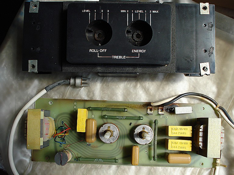 |
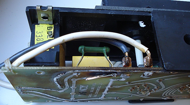
| Fig.2, Tannoy crossover for HDP 385a, left side, fault, see the burn and white ceramic resistor not original on the upper right, see the WB.3112a on the left, the round WC.3342 below and the WC.3380 on the right |
False, mistaken, fake, invented, and often malicious schematics
Have you ever seen a wiring diagram signed by Roy Grant, by Ray Lumley, by David Charles St. John Manley, by Colin Wonfor, by Glenn Croft or by Ronald Rackham and Guy Ruppert Fountain?
NO, They don't exist!
It was a typical behaviour of the English HiFi manufacturers not to distribute the wiring diagrams, the speaker construction plans and not even the service s for assistance services.
Those who have been involved in HiFi since the tube days know this, today's kids have to say it out loud.
At least 90% of the wiring diagrams of HiFi British production since the 60's are false, the same for the construction plans, whoever says otherwise is in bad faith.
Probably the only orignal drawing of Tannoy xover is this one, 12inchs. Notable exceptions are VTL book, Leak and Quad and maybe we miss another brand.
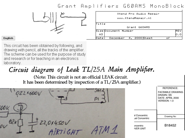 |
| Fig.3, important, but rare exceptions, someone claims that the schematics are not original, and we must thanks a lot the unknown designer for their precious work |
It's a completely different matter with the big tube HiFi brands, they boasted of the schemes they used and produced exhaustive reports and services manual, such as Marantz, McIntosh, Dynaco, Acrosound, Audio Research, etc.
Sorry but more and more web pages are fake, and someone does a business with this, be careful. See this comment in an Audio forum.
by Reffc at 01-04-2017, 18:28
The information posted comes from Tannoy. The letter is reproduced on Han's site.
Usual caveats in place of course but here's Phil Shorts investigations into tweaking the short horn DC's.. http://www.hilberink.nl/codehans/tannoy53.htm
Alas, that doesn't make it right, neither is it right!;) Ahhh, the perils of t'ut interweb :doh:
The explanation for the autoformers given there isn't strictly correct either. They were there to impedance match the drive units, not just for reasons of energy which can be got around by other means. Also, the input (green) winding of the input is most certainly not 4mH to ground. That is one of those errors which has plagued Tannoy internet crossover schematics and now I see where it originated! The LF value commonly ascribed to 315 HPDs is also wrong. It is not 1.2mH. It may be for the ceramic magnet version (but that I doubt) but it is most certainly the wrong value for the HPDs.
Again, Tannoy never originally published T&S specs because they simply didn't exist at the time and the letter refers to the values for the HPD, provided many years after the fact. It very much looks like the person who wrote that letter just assumed that the later ones would be the same. They can't be unless someone re-wrote the laws of physics in the intervening period. That can be proved. How can you have the same T&S parameters when different magnets and different horns were used? The Fs differs, the BL factors differs etc etc etc.
You can sometimes lead a horse to water but when people keep on insisting that duff information is correct, I have to shake my head and just give up. Hopefully people looking in will not be tempted to run with information gleaned from sources which do not ascribe the true values to fact (ie measurement). Paul.
Before any restoration is better have the "original" schematics, and, eventually, the upgrade from producer. If unavailable you can draw by pencil with a reverse engineering, with old tube equipments quite easy, with modern SMD quite impossible. In this case there is a web site with more and more schematics.
Someone as the following claim to be a design, an invention, others pass themselves off as originals. A good website should warn users, but instead some do the opposite.
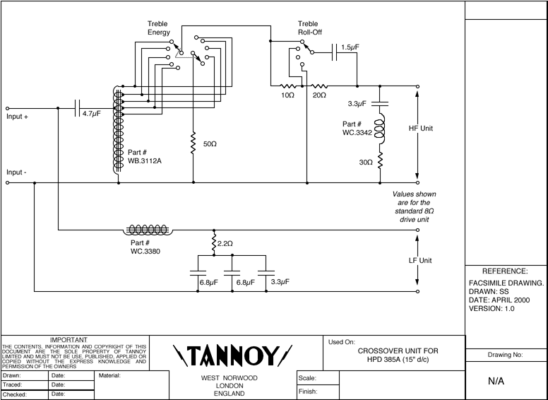 |
| Fig.4, claimed as Facsimile Drawing, the schematics of Tannoy crossover for the 15 inches HDP 385, the values of chokes MISSING. For WB.3112a the wire to ground is Black, the opposite site is Red |
Checking accurately the previous shown crossover I find all values of R and C confirmed (someone do an accurate reverse engineering, thanks), so the only problem is the 2.2 ohm dead but also ....
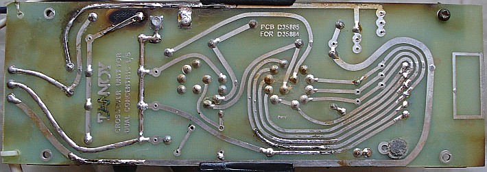
See below, the solder side of the left channel and compare with first figure. See the point n.1, oxidation on the label, current not pass here but if you have a copper 2mm large and 0.035 mm thickness for the woofer it is a big problem.
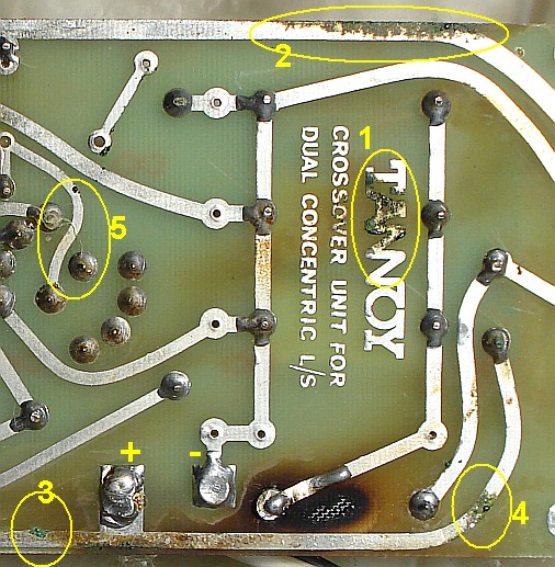 |
| Fig.5, PCB crossover copper oxidation, problems are n.2 and n.3. Probably n.4 is a cut! N.5 are a spare wire? |
The point n.3 is a small problem, only part of copper is oxidized (but remember the 0.22 mm!!), the point n.2 is a big problem long path have oxidation, and finally the point n.4 is probably cut by oxidation. See point n.5 it a spare wire with a bad link between the steps of selector, must be removed.
I forgot, but you know, the copper as metal is a very good current carrier, only Ag is better, but ANY metal oxide is an insulator or a semiconductor as a diode.
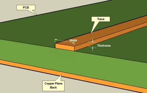 |
| Fig.6, common PCB thickness: 1 oz/ft2=0.035mm, 2 oz/ft2=0.071mm, 3 oz/ft2=0.105mm |
Please AVOID use of PCB to build a crossover, the standard PCB copper have 0.035 mm of thickness, the practically impossible-to-find 3 oz have 0.105 mm (3 oz/ft2). Doing some calculation, using the scarce 3 oz thickness and 2mm width 2*0.105=0.21 mm2. WHY you buy an exoteric 1000e/meter speaker cable and after pass current in a 0.2mm2 wire? Are you crazy?
Or if you really need the PCB to build a xover please do similar to top TDL, KEF, Rogers speaker, see this example.
A long discussion on PCB trace width, here.
Having schematics, the repair
Before proceeding you must be careful; ANY change to historic and vintage HiFi will reset the value for "a collector" who seek/need only original goods in its entirety parts. If you need to repair equipment like this one you should use original parts (with great effort and expense to find it), almost like a historical car.
Having I have the idea to unsolder all chokes and measure. To better reproduce one you need: form and dimension of laminated E shape, thickness of copper wire, R measured in DC, L measured in opportune frequency, probably weight, and some photo. Be careful these chokes have a gap of cork.
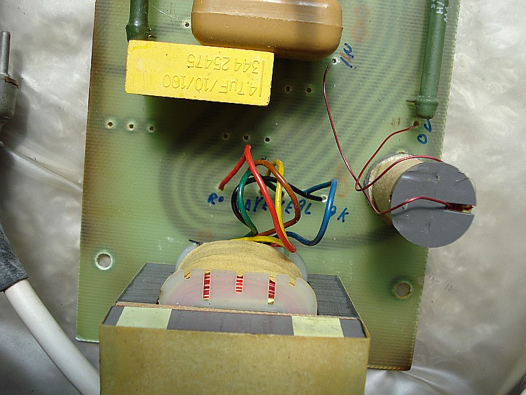 |
| Fig.7, the WB.3112a is an auto-transformer, never remove it from the circuit. They are rarer than Greek Attic Black Figure vessel and essential for the function of filter, as planned |
About the auto-transformer I must cite one other Audio forum.
by Bare, Canada, at 13th April 2013, 05:01 PM
NO! you Cannot live without the Autoformer.
Sure it will work well without it...
but not even close to what it should/could sound like.. Been there tried it.. Repeatedly.
Depends entirely on how high, or low, one sets one's personal acceptance bar :-)
Having said that.. there are at least 2 bespoke makers who supply decent reproductions of the complete Crossover.. Not free though. Google is useful.
The oem design autoformer is a' Reactive' component and the crossover circuit was Voiced with it. Substituting a simple coil produces audibly different result.. period.
But Hey! fill yer boots trying.. Many have :-)
by Charles Darwin, Lockwood Audio, 14th April 2013, 01:35 PM
Short answer: You don't.
Long answer: You'd have to have them custom wound for you. This will get expensive.
We have thus deleted from the discussion at least 10 sellers of Tannoy crossovers that we find on the internet, without autotransformer and that have bought their homes with your money.
First one, dimensions. With those you can buy an opportune E shape iron. Select the thinner and best iron materials.
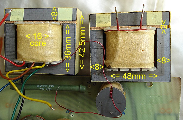 |
| Fig.8, Please see also the construction method, with paper, gap, and so on |
Next step, the weight. Using a laboratory balance is better.
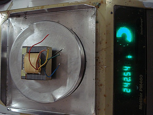 |
| Fig.9, 242.54g for the WB3112a auto-transformer |
Next step, the DC resistance. Also using a laboratory multimeter, Agilent 34401a, with null-ohm setting.
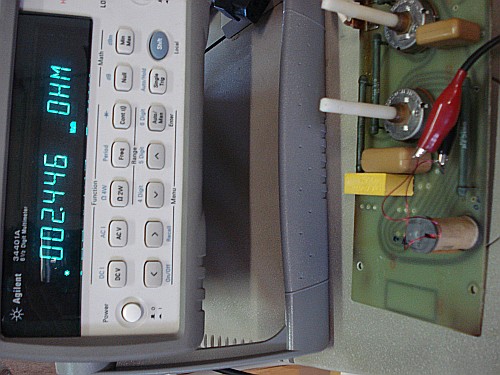 |
| Fig.10, 2.446 ohm for the Wc3342, part of the resonance filter, but for correct measure the "null" function must be used |
Next step, the wire thickness, measured with micrometer. More the measure of inductance at 1000Hz, not show here, using Nuova Elettronica, ZRLC meter, kit LX-1746 (see in the middle of this page).
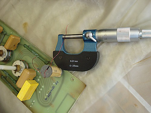 |
| Fig.11, 0.47 mm for the copper wire, varnished, of the Wc.3342 |
Choke values, OK
In previous the figures of measurement procedure for the 3 chokes. Following the results (estimated accuracy, with standard, better of 1.0%).
| mark/code | color | wire Ø (mm) |
DC resistance (ohm) |
inductance (mH) |
weight (g) |
|---|---|---|---|---|---|
| WB.3112a, black vs. | red | ? | 1.05 | 9.62 | 242.5 |
| orange | ? | 0.83 | 6.46 | ||
| yellow | ? | 0.72 | 4.46 | ||
| green/input | ? | 0.56 | 3.15 | ||
| blue | ? | 0.48 | 2.25 | ||
| WC.3380 | 1.03 | 0.25 | 2.38 | 237.8 | |
| WC.3342 | 0.47 | 2.24 | 0.70 | ? |
Sorry for lack of wire diameter of WB.3112a, but to measure it the transformer must be dismantled and the owner do not like it.
If you still want a demonstration of how necessary the autotransformer is in this design, after Lockwood's lapidary statement, read this page, the obtained values are a little different form mine. In other web page of J&K Audio a pair of auto-transformer was sell for $160. Be careful on fake crossover manufacturers (he/she have bought their homes with your money).
The paths on the PCB must be rewired, the 2.2 ohm must be changed with one similar to original. The 2.2 ohm was the main problem on this crossover family, probably for a momentary fault on one of the 3 capacitors, so is better change with a 5W or 7W type.
 |
| Fig.12, PCB repair only, oxidation removed, path rewired, some soldering |
Partially solved the problem of oxidized tracks we pass to replace the burnt resistance.
 |
| Fig.13, 2.2ohm, 5W, very very similar to original, with a lot of space for dissipation |
Repair complete, but can anything be done to improve this crossover?
Remember that any change could reset the value of the object for a true collector, but something can be done.
Tweeter RLC: The RLC filter in parallel with the tweeter is a resonant circuit. Its values depend on the electrical (coil) and mechanical (dome, suspension, horn load) parameters of the tweeter, adjusting it if you change the component is difficult. The one in fig.4, mounted, resonates at 3311 Hz with a Q of 0.485, which as you know depends on R.
Resistors: if the crossover mounts the resistors in Figure 14, do not touch anything. They are very good wire resistors, on ceramics tube, one layer of winding, they bear at least twice the declared power.
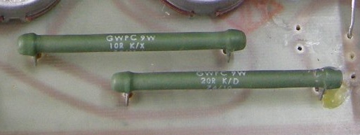 |
| Fig.14, GWPC resistor, very best choice for xover, don't change |
Selectors: amazingly, the switches (probably a Lorin Electronics) after 50 years are still in good condition on the various crossovers I have seen but can causing problems. Due to their nature of sliding contacts, they can be cleaned, without disassembling them, by spray some dry contact cleaner in one the 4 holes and by rotating them by hand in all positions, slowly and gently, at least 20/30 times. They should not be desoldered as you can damage the plastic that holds the various pins in place. They are found, identical, on the various distributors of electronics but I can not say how many years will last.
Wiring: probably there are 50 books and 76.451.000 pages on Google with text on speaker cables, can we write more? Fortunately Wikipedia exist and I can suggest reading this page. Or the beautiful Wirebusters of Roger Russel. Remember the cable NOT SOUND but an electrically wrong cable con IMPAIRS the sound (probably a very bad choice can destroy the source with parasitic oscillation, or similar one). In the crossover of Fig.1 you can change both the cable from the binding post to the crossover and the cable to the speaker. A real upgrade is to go from 3 to 4 wires to the speaker (pay attention to the phase) with a small modification to the speaker itself. I don't usually suggest brands, but the use of vintage QED cables produces good results. Please avoid the use of Faston, better a good soldering with Stannol LMP HS10 Sn62Pb36Ag2 soldering alloy.
Printed circuit board: the main problem of this crossover is the too thin and too long tracks in the PCB. The complex/final solution would be to rebuild it with the same components but with the point-to-point wiring technique. An alternative, but useful, is to fortify the tracks by adding 1mm2 solid-core wire over them with careful soldering. A careful reading of the schematic and the PCB shows that fortifying about half of the tracks is sufficient.
Dust cup: If you use the speaker grilles when the speaker are NOT in use some users recommend removing the dust dome. There are a few discussions on the Audio blogs but they seem to be almost all positive. As we know the Tannoy tweeter is actually a real horn, made of aluminium, which after 50 years you will see oxidized, bleached, once the dust cover is removed. The horn surface, the small holes, the rear must be metal polishing to smooth out the surface. No treble horn I have ever seen mounts a dust cover, not Klipsch, not Altec, not Electro-Voice, not Avantgarde, not Cessaro, not Acapella, not Pnoe, of course nor JBL! There are some wonderful reconstructions of these dual concentric on the internet that start with cleaning this horn.
Are you sceptical about the dust cover? take a close look at this page on a Monitor Silver from a famous Japanese shop.
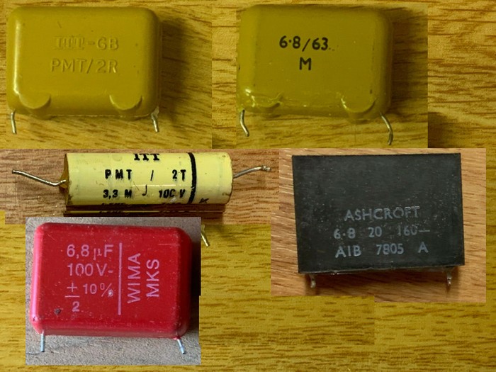 |
| Fig.15, some original, vintage capacitor, of Tannoy crossover. The photo come from a famous Ebay seller, Mark Pitcher, Hampshire, United Kingdom, thanks a lot. Ashcroft brand is dead, also ITT don't produce anymore audio capacitors |
Capacitors: here the insults are wasted, the offences abound, the gurus (of the keyboard) spit their truths, the dispensers of the Tables of the Law write them down, it comes to threats if you do not agree with their choices, prestigious brands are denigrated by those who have never even seen them in photos, there is only one thing to say "after testing 9 capacitors to have 4 perfect, have you ever heard what happens reassembling the Sprague Bumblebee paper-in-oil 0.1 uF capacitor on a Marantz 8b?", NO? Quiet please.
The best thing to do is to disassemble, one at a time, the capacitors, measure them with 2 different RLC meter at 1KHz/10KHz, better if professional, supply at label voltage through 100Kohm resistor for 1h and measure the final voltage on that resistor, and if they are in good condition reassemble them. We must mention another Audio blog:
by VanArn, Melbourne, at at July 30, 2018
I have measured a batch of capacitors kindly sent to me by StereoNet member Kranky. These are from a Tannoy HPD crossover network. All the capacitors have D, Q and ESR figures that indicate that the dielectric is polyester film. The tolerances were within the 10% range with the majority of them, well under 5%
Capacitors suggestion: the first thing you should not do is mixing several brands of capacitors on the same crossover. The second thing to do is to consider that this is a circuit subject to strong vibrations, produced by the speakers and produced by the signal, we have to read a paper by Clarity-Cap. The shape of the originals is perfect, note the little legs under the ITT's. The same shape should be looked for in the replacements. If the IITs are out of spec you can look for NOS on the internet, but even these need to be measured carefully (we'll write a page for that). A good choice are the Wima MKP-10, you can find 100V ones of the right size.>/p>
If the circuit has not been tampered with, its values (of that crossover, not those on the Internet) should be respected, read the previous note on the RLC circuit. If the correct capacitance value is not available, use 2 cond. in parallel with values about half of that (7=4.7+2.2 NOT 7=5.6+1.2).
Insult Duelund too if you can! They make capacitors specifically for 100Vdc crossovers (Duelund CAST and RS series, specifically designed for loudspeaker), i.e. 50 to 100V isolation values should be used for a speaker filter, NOT more.
Tweeter: if after all this work you don't like the sound of your 15 inches (as someone in some blog has the courage to say) maybe you have in your hands a product of Dr. Victor Frankenstein, that is a coaxial that has been badly assembled with different pieces (tweeter of 8 or 10 or 12 and maybe 15 ohm, with or without ring spacer, with inverted phase, surely aftermarket ....) in order to sell it at 2000 euros. Around the world there are a couple of people who could rebuild an "almost original" but ask first the cost.
As previous stated the PCB paths are too small and today is better the biwiring design. Also in this manner we can obtain 4 wires to speaker. Modify this crossover is not difficult, see the figure below.
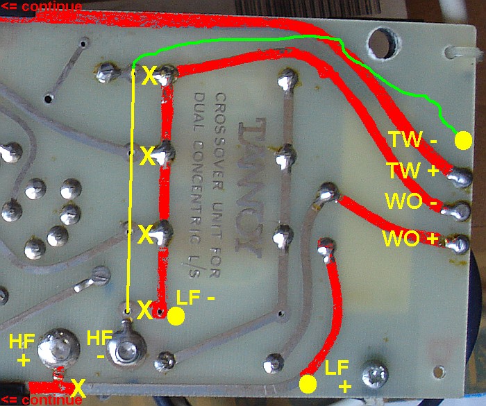 |
| Very Very suggested PCB modify to build a BiWiring and obtain more current |
The modify is very suggested, add a solid-core wire over the path reduce resistance and transport better the current, the wires to speaker are 4 having the connector 4 pins!
Donations if you have a Bitcoin wallet
If you have a nice fat wallet you can send a few cents to this code 1ETv1mJTZTB7EiXwZkucF2BTA512Rkaw6 maybe with a message (be careful to the transaction cost, send 0.1 and pay 0.01 is not a good idea).
1ETv1mJTZTB7EiXwZkucF2BTA512Rkaw6 <== my code , Thank you.
Donations if you have not a Bitcoin wallet
If you like this work and measures you can make a small donation of Bitcoin. You do not need a wallet to make a donation, indeed even those who have Bitcoin wallet is better to pass for a web site that "gift" currency since this does not have a transaction cost.
To make a donation you must use some of your web-time on a Bitcoin Faucet, please go to Kickasstraffic.com, enter my code 1ETv1mJTZTB7EiXwZkucF2BTA512Rkaw6 into empty cell and press "Start Earning", a new sub-page appear, do not touch other then the last 2 buttons in lower right corner "Surf Ads" and "Active Window Ads".
If appear a tweet asking to register use the lower right corner button "Close", solve the Captcha and proceed. Of course any next page if different but I suggest you to stay more time possible reading pages and advertisement to produce Bitcoin (1/100000 I suppose) for me.
Be careful, do not use roulette, dices, casino and other stealing web site, as claim of supposed infection. We use Kaspersky Free Antivirus by 2 years without problems.
1ETv1mJTZTB7EiXwZkucF2BTA512Rkaw6 <== my code , Thank you.
| In the last years at Universita' Degli Studi di Roma La Sapienza |
Dr. G. Visco already contract professor for Chemistry in Environment & Cultural Heritage into --> |
Corso di Laurea in: Scienze Applicate ai Beni Culturali ed alla Diagnostica per la loro Conservazione |