|
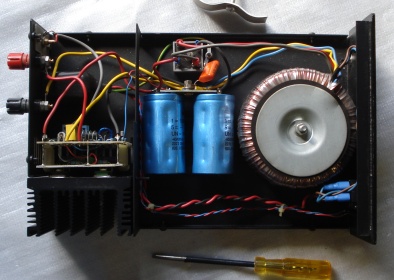
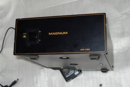
| fig.1, two mono amplifier, lateral mosfet based, from Magnum UK, probably 125W, in working condition |
All trademarks mentioned and links are presented here for informational purposes only and to confirm statements made by the author. The author of these pages DOES NOT receive any remuneration from the mentioned brands and the listed links.
In any case if you decide to use the suggestions on this page you do so at your own risk. Repairing electronic equipments, even just opening it, can put your life at risk, so don't do it.
If you do not accept and/or not understand the statements in this disclaimer, written in blue, exit from this page immediately.
Everything exposed in this web page is only a suggestion, probably you won't obtain the aim from you prefixed following it.
Be carefull, a true collector is looking for a) original items without any replaced parts, and with all accessories b) or if a Critical Restoration has been done that it is possible to go back to the original version.
To reply we cite a text of Colin Wonfor the designer of Magnum: I started life in my career as a chemist I hated it my hobby was electronics so after I graduated I went back to Uni to study Electronics, then at 50 I went on to Scotland and studied computer science I hated it. My Grandad and Dad were both electronic engineers so it is in my blood. (from Diyaudio).
Also I am a chemist with the hobby of HiFi, tube amp, and restoration from my early life. With the hobby of restoration I have the opportunity of "ear" some equipments impossible to buy for me.
Here a text on the history of the brand:
Anthony Colin Magnum Ltd was founded by Tony Relph who was also one of the co-founders of Rega. Rega is the abbreviation of the names RElph and Gandy. Tony Relph went on to found A. C. Magnum. Tony Relph has since retired and these amplifiers are no longer manufacturer. Magnum used Colin Wonfor circuit designs and there was definitely some collaboration between Colin Wonfor and Tony Relph at the beginning. Maybe the company name was actually stands for Anthony. Colin. Magnum (just guessing here but it would be plausible?) (from Audiokarma).
Some months after there is a reply from Colin Wonfor the owner and designer of Magnum:
Sorry No, this is wrong, Magnum was formed from my company MIH, which became Pro-Ac Magnum, then Tony Relph joined me as a business guru, then after 3 yrs managed after locking me out after a holiday stole the company and I was force to take legal action for use of some patents and stealing my company. Meanwhile I started Inca Tech producing no electronics until the legal action was resolved but the world first Gold Plated Power Connectors for the audio world, now be warned never share a company 50/50 if you have started it you partner may not be so trustworthy as you. And for folk out there here is a rough list of other things I have designed. In order: Pushpull 1 Germanium Amp at 1971 , V1 Tube amp at 1972 , 12W Single Ended A Class at 1974 , MIH 100W at 1975 , MIH 400W, ProAc stereo 100w at 1980 , ProAc 3 Channel 100W , Magnum A100, 400W at 1982 , Magnum A200 , Magnum Pre-amps , Inca Tech Sabre Iss 1 at 1983 , Inca Tech Prelude , Inca Tech Claymore 1 at 1983 , Inca Tech Claymore Gold , Inca Tech Claymore S , Inca Tech Claymore 2 , Inca Tech FMT Tuner , Inca Tech IT50,IT100,IT200 , Inca Tech IT1P preamp , Inca Tech Sabre Iss 2 , Inca Tech Dirk , Inca Design ID25,ID50,ID75 , Inca Tech MSB (a monster) , Inca Design Oberon Classic , Inca Design Oberon (standard) , Lescon , Oxford Acoustic's "Mystic" , TOCA SECA 20W,50W,100W,200W,300W single ended class A,s at 1995 , TOCA I75 , TOCA Pre A , TOCA 75W , Tellurium Q Cables at 2009 , Tellurium Q, A Class 20W, 100W at 2011 , Tellurium Q Headphone/Phono Amp , Tellurium Q Pre-Amp , Products worked on Naim Nait 5i , other bits also for Naim and Cambridge Audio at 2008- 2010, Colin Wonfor, Jul 14, 2012. (more from Audiokarma)
More information on A.C. Magnum are available with a simple search, unfortunately today the company is "dissolved", see Companycheck UK
In 1985 Hitachi design power mosfet and publish a databook 362 pages of with some application circuits. See the cover page below and from a scan of original.
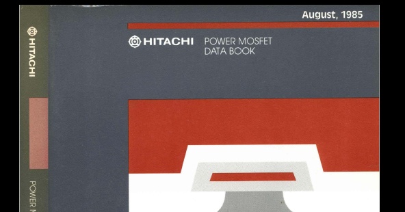 |
| fig.2, the 1985 Hitachi Power Mosfet Data Book, download here (.pdf 23.5MB) |
One of the most interesting characteristic of this Hitachi semiconductors are: In power MOS FETs, in contrast with bipolar transistors, the switching time is not influenced by temperature, and the circuit design will be easier.
This characteristic permit to build a very simple power stage, as the following published in 1986 in an electronic journal. See the photo below, a very small number of components!
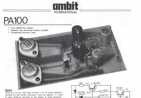 |
| fig.3, a paper from Ambit, a 100W ?? power amp with 2 FET only, here (.pdf 1.5MB) |
More conservative and interesting is the circuit for a 100W power amplifier inside application-notes of Hitachi (here .pdf 1.4MB). SEE this schematics, you can find in more and more, cheap or expensive power amplifier, from a small brand up to exoteric one, produced without reinvent the wheel!
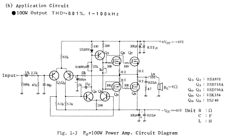 |
| fig.4, the schematic of a 100W from Hitachi data sheet, 4 MosFet, 65V supply |
One of the major lacks in the design in cheap or exoteric audio FET amplifier is the missing "source resistor". Some producer can select 6 mosfet in a lot of 100, with a time costly procedure and expensive instrument (as Tektronix 576. Tek 577, or new Sony-Tek 370-371, HP 4155, Agilent B1505A) to build an amplifier.
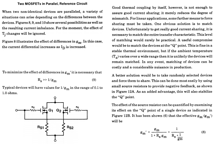 |
| fig.5, Rudy Severns, MosPower Application Handbook, 1985, page 160-163 (.pdf 30MB) |
From the book cited above you can read more on this small resistor. Are there in our Magnum? Inside the book there is an entire paragraph to describe How to Test a FET, not easy to do.
The 2 MF-125 work, quite well, but no service was done from 20 years. Reading previous "dissolved company" there is non-way to obtain schematics, so it is necessary design with pencil and magnifier lens.
But ...... Hitachi produced some HiFi equipments, and the famous HMA-6500, using the MosFet already cited with more complicate circuit (DC input balance, AC balance, speaker protection circuit, MosFet protection, and so on).
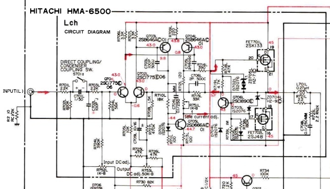 |
| fig.6, the complicate output stage of HMA-6500, here the circuit in HigRes, here the service manual |
Start with a dismantle of "one" of the amplifier and check if there are differences with the other. Make photo and photo to check the construction quality and the parts to be update/modified.
 |
| fig.7, inside the MF-125, see the original resolution here |
See the original capacitor, tandem of 10000uF/63V.
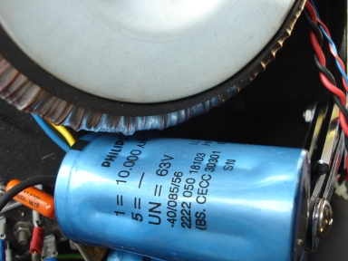 |
| fig.8, a good Philips is the original capacitor |
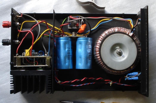
Interesting, the 25A/400V diode bridge, near the case ground, the 2 capacitors with signal ground in centre-star mode. Only one Philips 0.47uF/400V link case-ground to signal-ground.
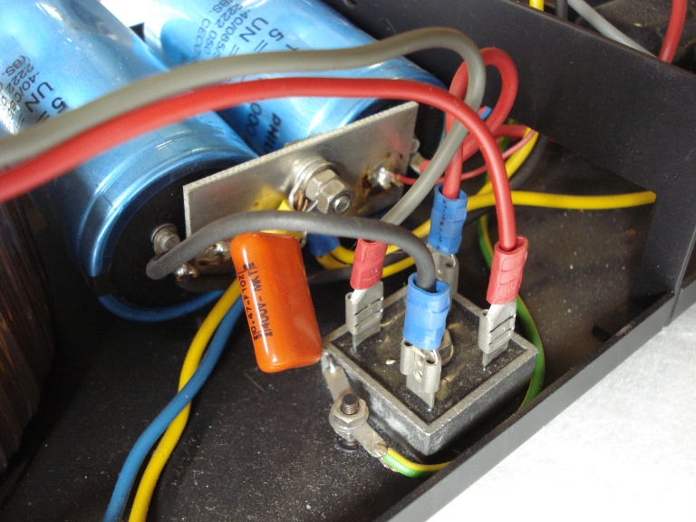 |
| fig.9, power supply module |
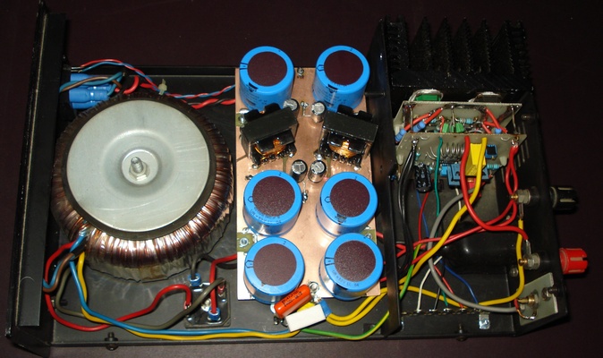
The output stage, see the 2 yellow wires as ground, one from centre-star ground to out jack, one to amplifier. Red the positive, grey the negative.
If you need to know more on "ground loop" you can read the paper of B. Whitlock, J. Fox, Ground Loops: The Rest of the Story by Jensen Transformers, Inc.
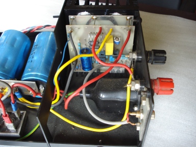 |
| fig.10, output, see the original resolution here |
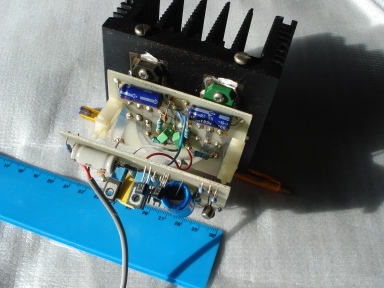
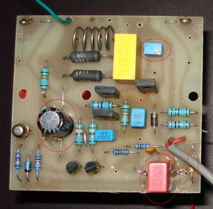
All amplifier module is a cube with a side of about 100mm, four layers, one is heatsink, one the MosFet fixed with screw and mica insulator, next layer the supply of MosFet connected to front layer, the driver stage, with 1.5mm wires. Compliment Colin a good idea.
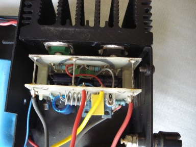 |
| fig.11, power module, see the original resolution here |
For ANY power amp. more then half of amplifier is "the transformer". In this case the 300W toroidal show a good quality. With 300W and with very efficient power stage (optimistic 25% for a A1 class and 60% for an AB class) we can obtain 180W on the load, with an A1 class probably we cannot obtain 75W (if heatsink not burn before).
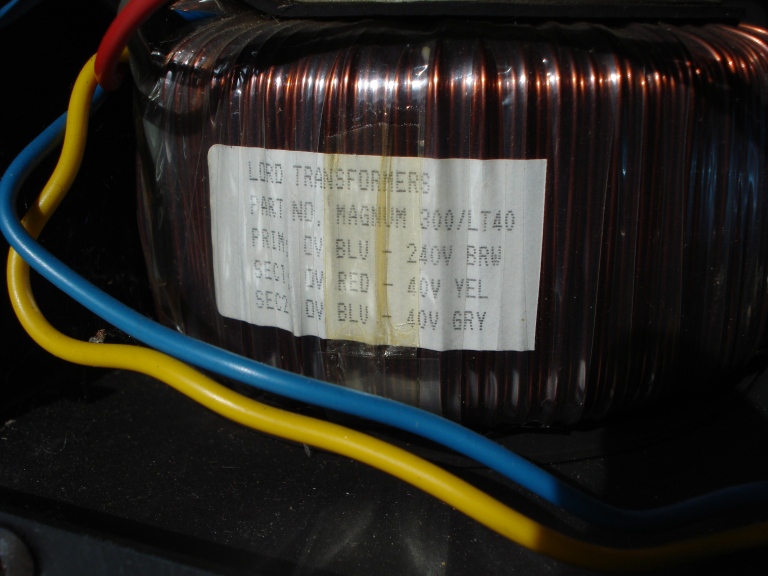 |
| fig.12, Lord Transformers UK, 300/LT40, build for Magnum, seem good quality parts |
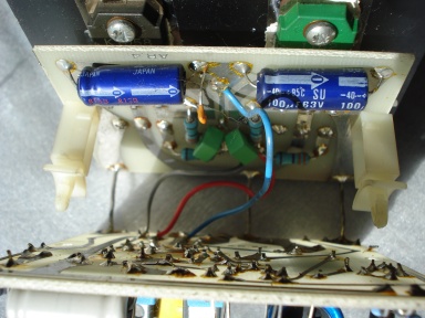
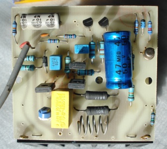
Opening the 2 clips we can detach the last 2 layers, please see the 2 green Wima capacitors, the 2 axial blue cap. and the small brown ceramic cap. on the ground.
 |
| fig.13, power module, see the original resolution here |
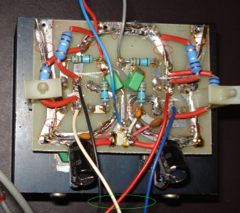
The driver and input layer. See the poor grey capacitor 10uF/63V Not Polarized (NP) as input with a too low 10K input resistor. See the blue 47uF/50V NP in the feedback path. See the 10R and the yellow 0.1uf/250V of the Zobel circuit, near the poor small 1K trimmer.
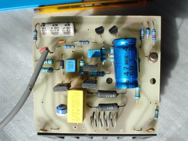 |
| fig.14, the input PCB, see the original resolution here |
Finally the power board with two 100uF/63V, the gate resistors, with the FETs soldered directly to the board, but we need a better view after detach the two PCB.
We can see a big problem of thickness of PCB in the power module, usually the thickness of copper is 35um, in some case 70um, but here insufficient for the expected current!
 |
| fig.15, the output PCB, see the original resolution here |
There are not schematic of any A.C. Magnum in the major circuit database, we can find a few hand-made design.
This is a big problem to restore an equipment to original design. About 100 brands closed or sold in HiFi and some are bankrupt to maintain high the quality of products (as Marantz 10b or Agi 511a).
Can we suggest to modern, top quality brand (as Tsakiridis Devices, Auris Audio, Trafomatic Audio, NAT Aadio or Yamamoto Soundcraft) to produce and disseminate the "service manuals" almost 10 years after the end of production?
the as-is Schematic
Having a lot of time, DMM, RLC meter, magnifying glass, pencils and papers we can do a reverse engineering of this amplifier. Below the circuit as obtained from the amp. n.1, the other is identical, only the poor trimmer changed!
There are not schematic of any A.C. Magnum in the major circuit database, we can find a few hand-made design.
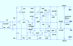  |
| fig.16, high resolution of: as-is schematic, original power supply |
As expected the power supply is very simple, and the amplifier schematic miss some components for cost reduction. Probably after read all the previous documents we can obtain a little better design whit a few euro.
As already said an amplifier for FM radio station, to move a robot's motor or for HiFi cannot be better of their power supply. Here the transformer is good, the bridge is OK but the smoothing can be better.
the upgrade
In the power circuit we can do better using a choke and capacitors in parallel in place of one single, do not forgot the bypass. more on amplifier side. Here the list of upgrade, probably in order of importance:
Running some tips and trick must be done to obtain "quality" in the upgrade.
the new schematic
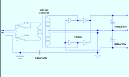
Below the new schematics for power supply, on the left, and for output stage, on the right. As usually you can download the HiRes version with a click.
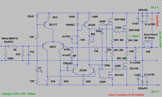 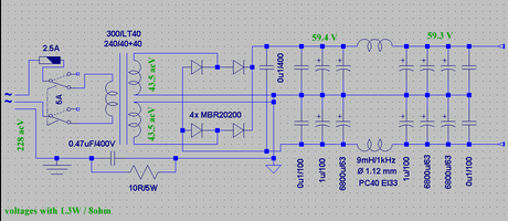 |
| fig.17, upgrade, modified version of schematic, and power supply in HigRes |
build the power supply on a PCB
There are 2 possibility: 1) design the PCB with one of the graphic software as FreePCB, and ask a service to produce it, but for only 2 parts is stupid, 2) build by self. We select the second one.
The rebuild start with the production of inductors (about 9mH), using EI33 form factor with PC40 ferrite, with 1mm2 enamelled copper wire, immersed in bicomponent resin is probably sufficient the carry 2x current coming from main transformer. Of course we can build by self or ..... find a winding service.
 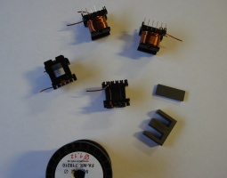 |
| fig.18, on the left the PCB, free of components and inductors on the right |
For PCB is better buy a FR4 copper clad laminated UL94-V0, with thickness of almost 70 micrometer (2 oz). Exist heavy copper, 4oz, 140 micrometer thickness not easy to find, never see in crossover or HiFi power module.
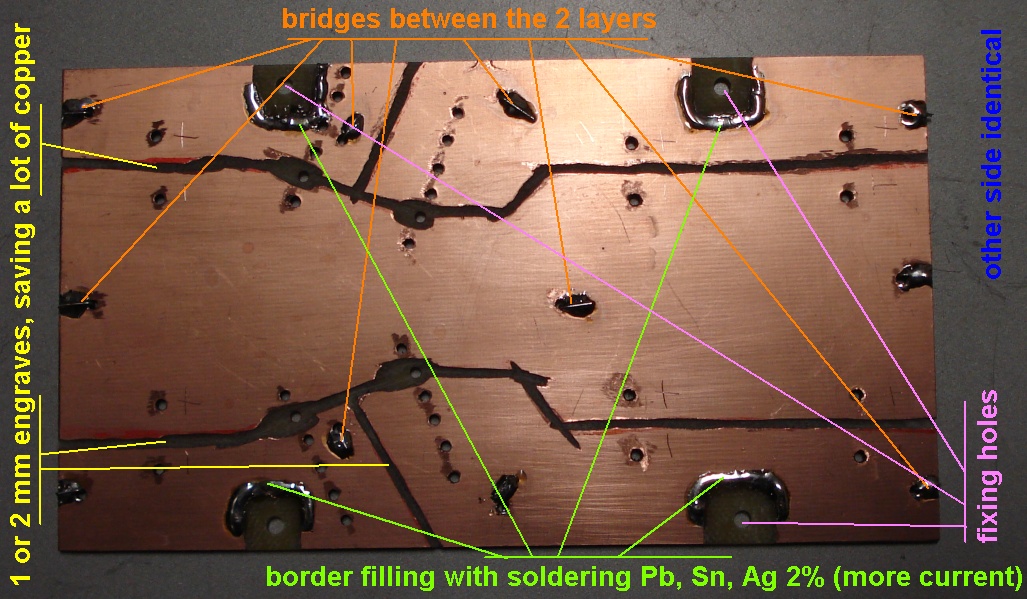
We use the 2oz dual layers. See the High Res photo to know the tips and tricks (between layers, border, etc.)!
Cut, engraved and soldered the PCB we can fix the component, using wires and turrets to made more bridges between layers.
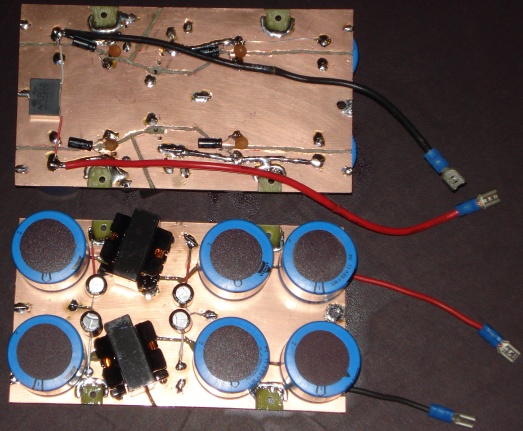 |
| fig.19, the 2 sides of new PCB, the small capacitors are on bottom side |
To build the PCB more and more was be done to maintain a large current capacity, almost 10A, see the last unsoldered wire on the top right. To fix the PCB we can use 4x 3x25mm screws (leave more the sufficient space for the bottom capacitors).
The 2x 16AWG wires is already fixed to first capacitor, on the right of the photo must be fixed the 2 wires to amplifier and the hole is to fix the screw for centre-star ground.
rebuild the amplifier circuit
The 2 PCB of amplifier are build by pencil and acid, not sure with a software, are sufficient but LACK on copper thickness. However it is easy to fix. Below the photo of the original.
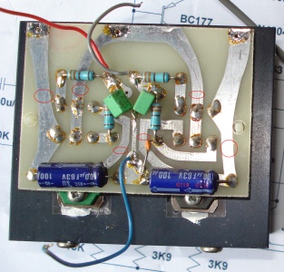  |
| fig.20, on the left the FET PCB before, on the right the FET PCB after upgrade |
There are some upgrade needed on the FET PCB show above, the main are:
The other PCB is the driver and input stage, see the photo before.
  |
| fig.21, on the left the driver PCB before, on the right the driver PCB after upgrade |
Only a few, but necessary, upgrade on the driver PCB shows in Fig.21:
fit all together
With more the 120W of output the wires inside must be tick as sufficient. Here was used the 14awg from bridge to first capacitor and 2x 16awg from power supply to FET PCB. All soldered on main capacitors not on copper foil. Below the photo.
 |
| fig.22, finally the MF-125 is ready, see full resolution photo |
On the right bottom corner there is a pin-strip with the wires connected to the 4 sources of FET to measure the bias current.
This is not a review or a stress test of the Magnum amplifier, only a few measures to check the upgrade, first the power on 8ohm, after the noise with input closed to 1000ohm, next the ripple on bridge and ripple on amply board (the pi-greek filter is in the middle!).
From the photo of Uni-T 81b, below, we have 32.6V at 1kHz, on resistive 8.1ohm load (calculate yourself the watts). In the meantime check and set the bias current, in this case (see problems below) at 30mA for every FET.
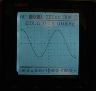 |
| fig.23, at full power on pure 8.1ohm load here |
the choke is necessary?
YES, but is better in common mode, only a few mH doing differences!. Having 32.6 acV as output we set the signal generator at -20db (about 3.25 acV) and wait 2 hours to stabilize the amplifier, as a burn-in.
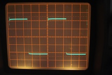
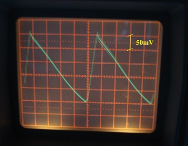 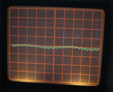 |
| fig.24, on the left the ripple after the bridge, + side: on the right the ripple on the power stage, same scope scale |
Only 9.5mH produce the signal on the right! the photo are not a top quality, we haven't time and patience to build a photographic set. We can see the sine wave modulating the ripple of power supply. Have you check your 50,000 euro equipment for this?
problems, problems, and more problems
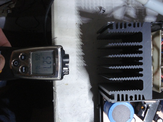
FIRST the heatsink, se the photo with measure, we have not word to describe, probably ridiculous is appropriate.
At the time of writing the top PC processor are the Intel i9 9980XE and the AMD Theradripper 2990WX with a TDP of 165W, have you see the heatsink capacity of those? With 4 heat pipeline, 7000 Rpm fan, copper base, and so on.
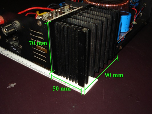 |
| fig.25, completely insufficient heatsink for 120W on 8ohm or 210W on 4ohm |
SECOND the temperature, we set bias current at 30mA but looking for in Internet we find suggestion for those "marvellous" lateral FET to 100mA, 120mA and someone suggest 150mA. Below the temperature after 2 hours, with 1.32W (-20db).
When the Magnum return to the owner we suggest to check temperature of "real life" often and if necessary reduce, unfortunately, the 30mA bias setting.
 |
| fig.26, room at 20 °C and heatsink at 52.7 °C after 2 hours at 1.3W (the Testo measure also the hot air flow, 22.6 °C, see photo) |
THIRD the frequency response, the one year old homo sapiens sapiens probably are able to recognise audio signal form 16 Hz to 20.000 Hz, but limits was reduced with age, adults are unable to hear above 16 kHz (H.F. Olson, Music Physics and Engineering, Dover Publications, 1967).
So is stupid produce an amplifier from 4 Hz to 100 kHz. The lower limit can help to reduce vinyl rumble with a cut, as example, at 12 or 15 Hz. The upper limit can be from 25 to 35 kHz to reproduce the second harmonic of 16 kHz (but you con not ear).
More, with a rising numbers of high frequency signal, from 5g to wireless, from Bluetooth to car remote command, the probability to obtain a signal of 50kHz is real (as signal battement, as frequency differences, as interfering fringes, e.g.).
Best way is use an high pass and low pass embedded by-design, in the circuit of the amplifier.
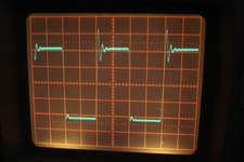 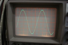 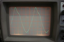 |
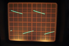
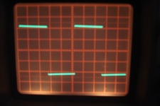
| fig.27, in top side the square wave at 100 Hz, at 1,000 Hz, at 10,000 Hz, in the bottom the square at 50,000 Hz (see the ringing), the sine wave at 1,000 Hz and the sine wave at |
See the bottom figures, the frequency response go to 200.000 Hz, completely out of any possible audio signal (of course the Later FET is used in witching power supply running often a 100 kHz or more).
The Lateral FET are very interesting to produce a "simple" and audiophile power amplifier, the best way is copy schematic from the Data Sheet or from Application Notes of the producer, Hitachi and today Renesas.
One of the major problems is the fake, false, poor, components. It is difficult to find "real" Renesas components but if are ready to pay almost 10 euro for one you can. When components become a Myth immediately starts the fake production, how many Mullard tube, New On Stock exits? Billions? But this small factory close in 1988! (Philips continued to use the brand name "Mullard" in the UK until 1988).
If you are going to produce an L-FET mono amplifier we suggest a 50-60W, with only 2 FETs, with a 300W toroidal transformer followed by a pi-greek common mode filter, with capacitance ratio 3 to 1 after choke an with a large, large, large heatsink to set the bias at 120mA (check if the drivers need also a small heatsink).
An interesting project, with PCB is in the famous Rod Elliott web site, the project 101 (probably C6, C9, C11 need a bypass, see my schematics, and the FET need the source resistor, 0.1ohm).
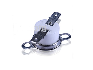 |
| fig.28, an example of bimetallic thermal switch |
See figure 25, there is not space to insert a thermal switch but in your new design, with large heatsink you surely find.
Donations if you have a Bitcoin wallet
If you have a nice fat wallet you can send a few cents to this code 1ETv1mJTZTB7EiXwZkucF2BTA512Rkaw6 maybe with a message (be careful to the transaction cost, send 0.1 and pay 0.01 is not a good idea).
1ETv1mJTZTB7EiXwZkucF2BTA512Rkaw6 <== my code , Thank you.
Donations if you have not a Bitcoin wallet
If you like this work and measures you can make a small donation of Bitcoin. You do not need a wallet to make a donation, indeed even those who have Bitcoin wallet is better to pass for a web site that "gift" currency since this does not have a transaction cost.
To make a donation you must use some of your web-time on a Bitcoin Faucet, please go to Kickasstraffic.com, enter my code 1ETv1mJTZTB7EiXwZkucF2BTA512Rkaw6 into empty cell and press "Start Earning", a new sub-page appear, do not touch other then the last 2 buttons in lower right corner "Surf Ads" and "Active Window Ads".
If appear a tweet asking to register use the lower right corner button "Close", solve the Captcha and proceed. Of course any next page if different but I suggest you to stay more time possible reading pages and advertisement to produce Bitcoin (1/100000 I suppose) for me.
Be careful, do not use roulette, dices, casino and other stealing web site, as claim of supposed infection. We use Kaspersky Free Antivirus by 2 years without problems.
1ETv1mJTZTB7EiXwZkucF2BTA512Rkaw6 <== my code , Thank you.
| In the last years at Universita' Degli Studi di Roma La Sapienza |
Dr. G. Visco already contract professor for Chemistry in Environment & Cultural Heritage into --> |
Corso di Laurea in: Scienze Applicate ai Beni Culturali ed alla Diagnostica per la loro Conservazione |