| read the discalimer | speaker history | what model ? | sending to me | crossover problems |
| the schematics | installed inductors | what resistors was used | brand and type of capacitors | new components |
| Inner-foil, Outer-foil | the bottom side | fix component | crossover fixing | some measure |
| how crossover work? | repair tweeter | download files | . | . |
All trademarks mentioned and links are presented here for informational purposes only and to confirm statements made by the author. The author of these pages DOES NOT receive any remuneration from the mentioned brands and the listed links.
In any case if you decide to use the suggestions on this page you do so at your own risk. Repairing electronic equipments, even just opening it, can put your life at risk, so don't do it.
If you do not accept and/or not understand the statements in this disclaimer, written in blue, exit this page immediately.
Everything exposed in this web page is only a suggestion, probably you won't obtain the aim from you prefixed following it.
A true collector is looking for a) original items without any replaced parts, b) or if a Critical Restoration has been done that it is possible to go back to the original version. Lacking the previous 2 statements the object (not only for me) has a value of zero euros.
Be very careful when buying a vintage, antique or historic loudspeaker. After 40 or 50 years, the magnets suffer from demagnetisation and the neoprene suspensions are now a wooden ring, the plissé and impregnated silk has opened up in the folds, and the foam, now sticky like bitumen, will drive the repairer crazy.
And the worst is yet to come: oversized broken coils, oval or square suspensions that are impossible to find, cardboard cones with impossible angles. And there is no cure for everything.
Beautiful speakers, with captivating sound when new, but a proper restoration can cost much more than the car itself, as in the case of this Fiat 500B.
I don't know how much these loudspeaker cost, nor do I know whether they were bought in a shop near home or 1,000 kilometres away, but let's take a look at some photos.
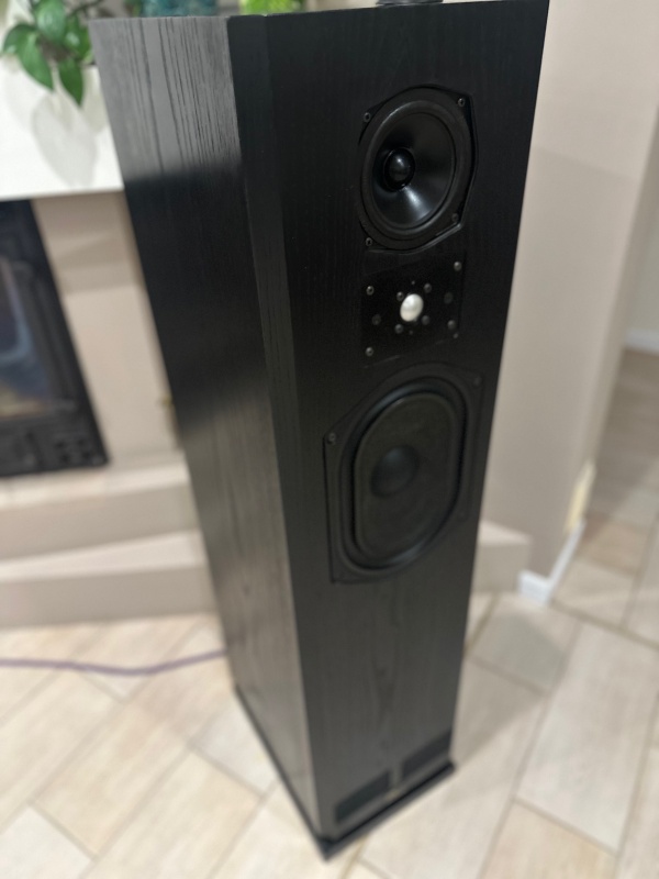 |
| Fig.1, a photo of the newly purchased TDLs, a beautiful black colour, they look perfect but sometimes there is a surprise inside |
If we had a few more photos, we might be able to identify the model and perhaps even the manufacturer (Fried had licensed production to external manufacturers).
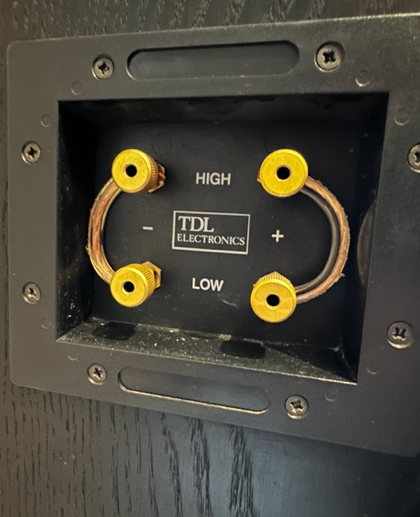 |
| Fig.2, the socket with the contacts, which are attractive and sturdy, does NOT need to be replaced, but the model number is missing and there is no "Made in England" label |
Perhaps there is something written inside the box, or on the crossover, or on the speakers.
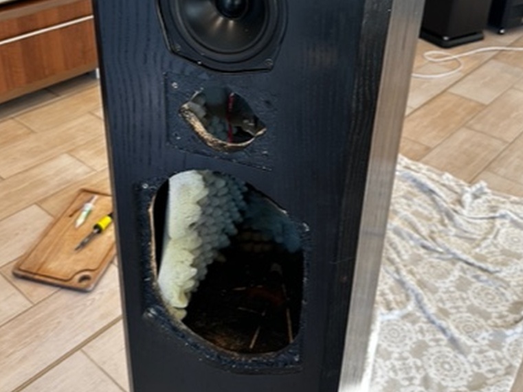 |
| Fig.3, removing the two drivers reveals the wood beneath the veneer, which is particleboard rather than MDF or HDF. Particleboard is a good material because it is amorphous and does not resonate in any particular direction, but it does not hold screws, so you will need to take action. However, the quality of the glue used by the manufacturer is crucial |
Another photo from inside clarifies the model and manufacturer.
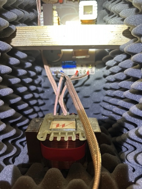 |
| Fig.4, perhaps the photo of the interior gives us more information: the large Mundorf inductor at the bottom and the coil at the top right show us a crossover of a different model from that seen into Studio Monitor 4, and the large crossbar between the two long walls of the cabinet tells us A.O.S., a German manufacturer under licence |
The photo above also shows us some different internal cables, which were certainly replaced during a previous repair. We need to decide whether to keep them, if they are of good quality, or replace them.
Sending a parcel seems like an easy thing to do. You can find great deals and prices online, but then you have to deal with IDIOTS against whom there is little defence.
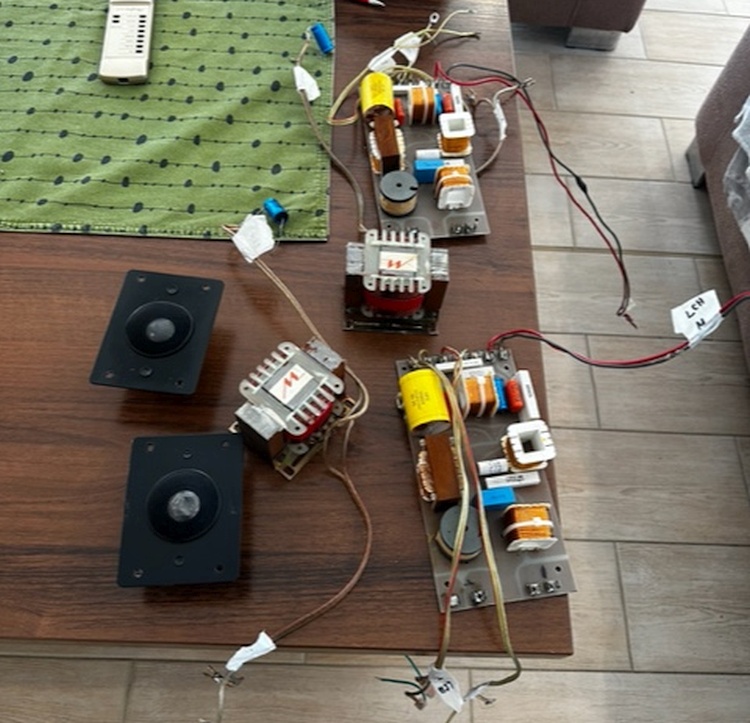 |
| Fig.5, the crossovers were just dismantled and are in good condition. It's strange that the coil laminated packs show some rust. We will look into this later. There is also a damaged tweeter |
Jacek packed it well and the components seem to be well protected. What more could you ask for?
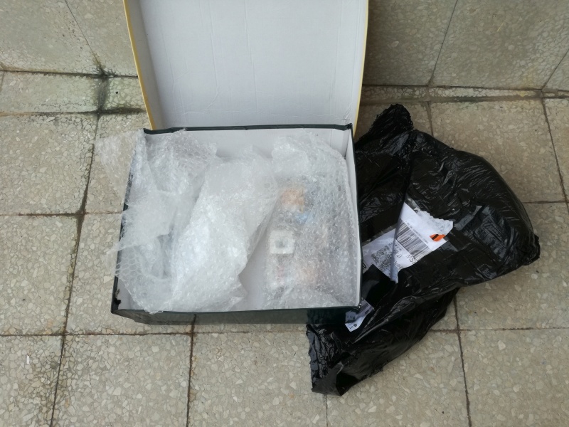 |
| Fig.6, the package just arrived. It's well packaged once again, but we'll look at the components later. With mouse-over let's look at a photo of the package as it was originally packaged |
Some problems arise in the factory, others arise during use due to vibrations, and unfortunately some arise during transport. Finding transport damage is easy: just compare the before and after photos.
Place your hand on a speaker playing music with energy at a high volume and you will feel the vibrations the crossover has experienced over years and years of music playback. I recommend Awakening by the Mahavishnu Orchestra or Thunderstruck by AC/DC for this test.
Truly well-designed crossovers have a layer of wax (TDL Monitor) to secure the components, or an excessive amount of cable ties, as in this example.
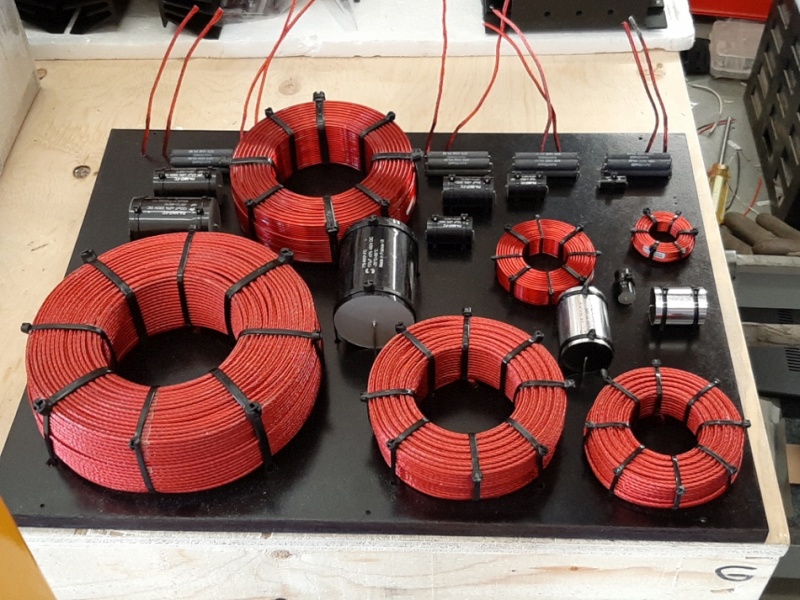 |
| Fig.7, here is an example of how components should be secured on a crossover, in this case a Solen kit. Another example, taken from the internet (thanks), shows that even the resistors are secured |
Opening the speaker often reveals one or more surprises.
 |
| Fig.8, you have to see this! Some genius detached the capacitor from the PCB and soldered it directly onto the woofer. Just a few vibrations and it's ready to short-circuit and break your expensive amplifier |
Now let's take a closer look at the problems with securing crossover components. Some of these problems are due to transport, but others are due to the construction itself.
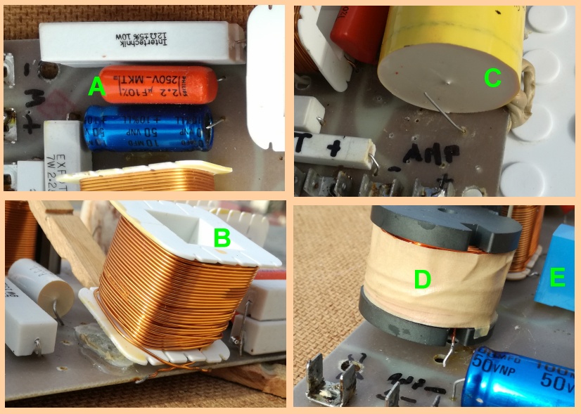 |
| Fig.9, the obsessive fastening of components as seen in the examples above would perhaps have prevented some scoundrel from damaging the crossover |
Let's look at the problems in the photo above:
a) The manufacturer is at fault for placing the midrange resistor near two capacitors (cutting a track to do this),
b) What did this coil do wrong to deserve a spot of glue instead of a cable tie? ?
c) There is transport damage, but only a spot of glue securing a fat capacitor (which was later repaired),
d) This heavy coil is not secured at all!
e) This capacitor has been left raised to allow it to vibrate better.
Before dismantling anything and carrying out any necessary repairs or replacements, we need to draw, understand and perhaps simulate the crossover on which we are going to work.
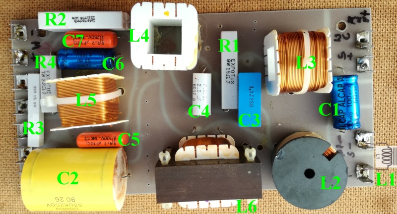 |
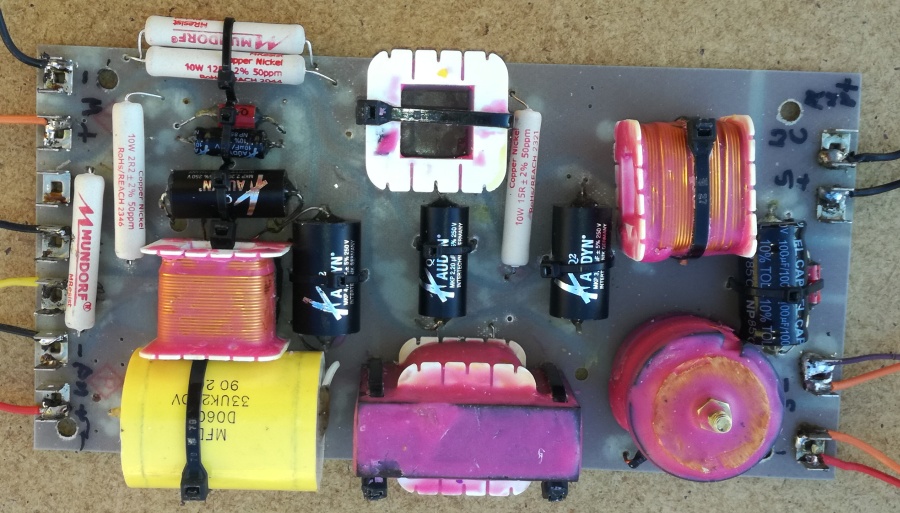
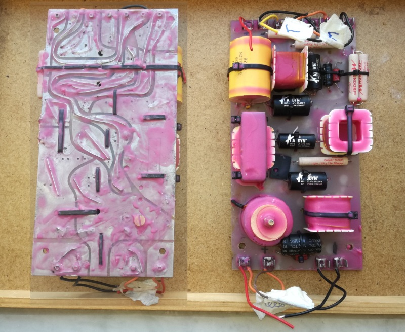
| Fig.10, first, let's take a photo of the TDL Monitor Compact crossover. Then, we will give the various crossover components a code so that we can identify them in the wiring diagram using the same code. Finally, we will dismantle and measure them, maintaining the code association. Here the high-resolution photo |
To draw an electrical circuit, all you need is a pencil, an eraser, and a sheet of paper. Then, starting from any external connections, you follow the tracks until, at a certain point in the process, the paths rejoin. I was taught how to reverse engineer even complex PCBs using that method (clearly you must be able to recognise each component individually).
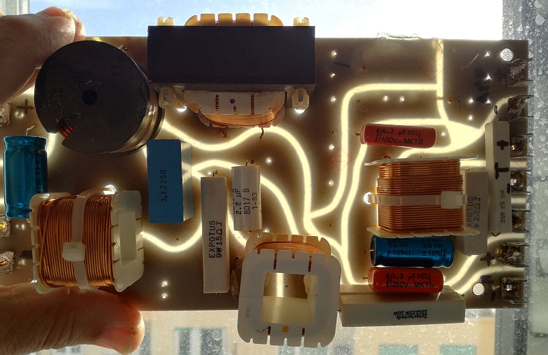 |
| Fig.11, in the transparency, you can see dozens of holes that have already been prepared for other crossover models, some with more components than others. Let's try using them to reposition our components and create more space |
Now you can draw the circuit. Check it several times before dismantling everything and figuring out how to reposition the components. In particular, make room for C5, C6 and C7, as these may increase in size. Once you have found the new positions, mark where you will drill holes to secure all the components more firmly, including the resistors if there is space.
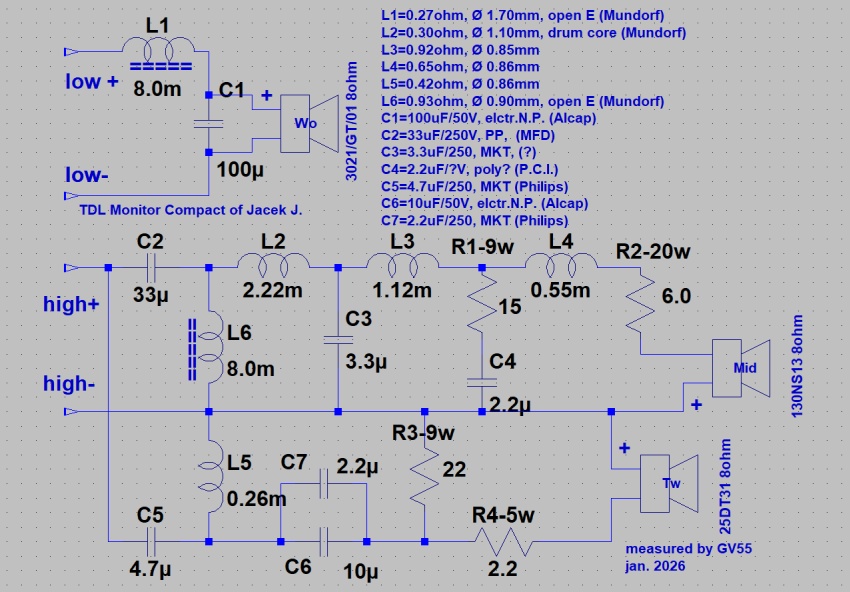 |
| Fig.12, finally, we can draw the electrical diagram of the crossover for Jacek J.'s TDL Monitor Compact, which is once again a little different from those found online. The files contain the diagram drawn with LTspice IV |
Now we unsolder all the components and analyse them one by one to decide whether to keep them or replace them.
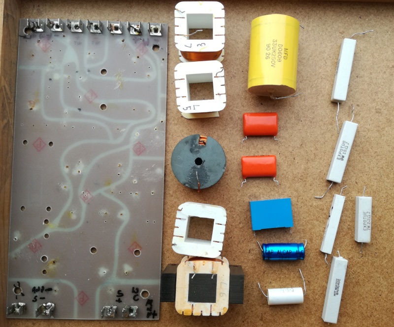 |
| Fig.13, once all the parts have been dismantled, we move on to measuring each component |
There are endless discussions about whether air-core or core-wound inductors are better, filling thousands of web pages and specialist magazines. As always, there are self-proclaimed experts who claim to know the truth. We would suggest that these people, who are well advanced in years, visit an audiologist or psychologist.
We are not interested in this debate. If Mr. I.M. Fried chose these inductors, who are we to argue? On blogs, I have seen so-called geniuses improve upon the work of Paul W. Klipsch, criticize a famous speaker by Arnold Wolf and colonel Richard Ranger, and upgrade the Patrician 800. If you're so good, why not start a company like Advent Corporation and become famous?
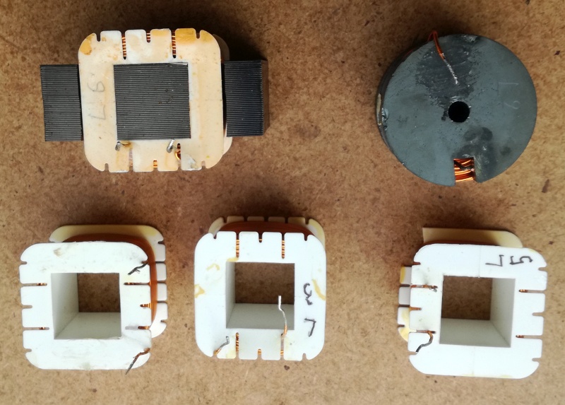 |
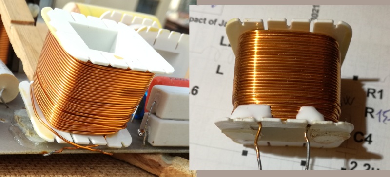
| Fig.14, Let's start with the inductors. Their position relative to each other is important in order to minimize mutual induction. Here we can see that they are all mounted correctly, 3 to produce a up-down field across the PCB, 1 north-south and 1 east-west. Apart from L4, which is slightly defective (already seen in B in Fig. 9), the others are excellent and should NOT be changed. However, they suffer from a problem common to 90% of crossovers: they are not impregnated. |
Now, let's look at the benefits of impregnating an inductor (unimpregnated transformers are not sold at all, in fact, the best ones are also encapsulated, such as McIntosh, Quad, and Jadis).
- Better insulation: Air is replaced with a material that has a significantly higher dielectric strength,
- Better mechanical properties: It binds wires and other components together, strengthening the structure,
- It improves moisture resistance and thermal stability, extending the life of the product,
- Reduced noise: Eliminates air pockets that can cause vibration and noise during operation,
- It is more resistant to external vibrations because it forms a single body.
We will use microcrystalline wax with a softening temperature of around 80°C. However, if we have some extra money, we could purchase the best audio inductors on the market.
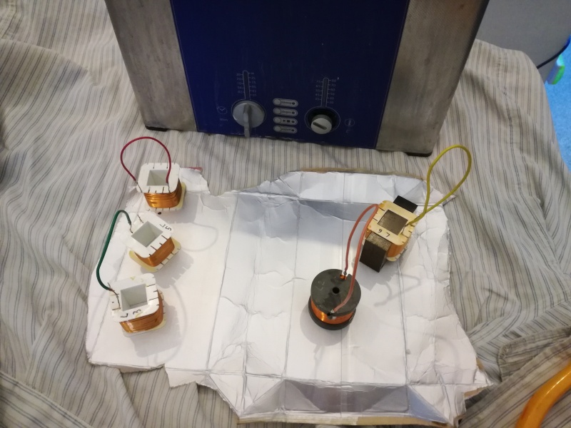 |
| Fig.15, the inductors are prepared for impregnation in an ultrasonic bath, 45KHz, for 60 seconds in order to extract air bubbles between the coils |
Heat the wax in an electric stove until it is completely liquefied. Be careful with the flames, as some waxes produce flammable vapors. Also, be careful of splashes of boiling wax. Wear heavy gloves and safety glasses.
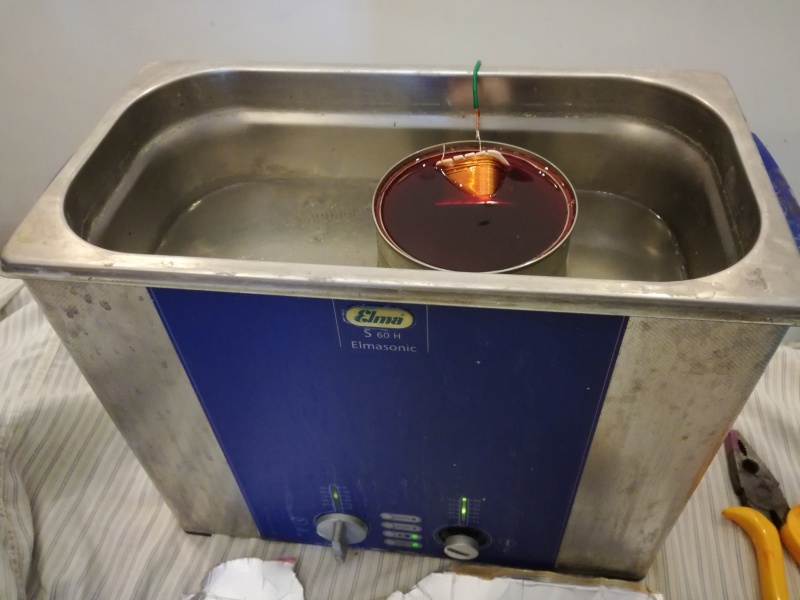 |
| Fig.16, here is the impregnation in molten wax. We use wires welded to the rheophores to handle the coils without burning ourselves |
Now the coils are ready to go back on the PCB. Try to secure them as best as possible by drilling lots of holes for the cable ties, making sure thet the holes are compatible with the PCB paths.
 |
| Fig.17, the coils secured with cable ties, we note that L5 (on the right) has been up moved towards C2 to leave more space for C6, C7 and R2, so C5 will need to be repositioned. Furthermore, L2 has been rigidly fixed with a 5 mm genuine brass bolt and a wooden washer to avoid tightening the ferrite too much |
We would like to remind you that we used excellent original coils. We will conclude this section with the measurements taken before impregnation. The crossover is now more stable and resistant to vibrations, and we have created more space.
| our code (brand) |
stated value (mH) |
form type | inductance (mH) |
resistance DCR (ohm) |
wire diameter (mm) |
weight (grams) |
inductance (mH) |
DCR resistance (ohm) |
wire diameter (mm) |
weight (grams) |
| L1 Mundorf |
? | open E core | 7.92 | 0.27 | 1.70 | 1956 | 8.08 | 0.27 | 1.71 | 1959 |
| L2 Mundorf |
? | drumcore | 2.23 | 0.27 | 1.10 | 170.7 | 2.21 | 0.31 | 1.08 | 174.1 |
| L3 ? |
? | aircore | 1.12 | 0.91 | 0.85 | 99.5 | 1.12 | 0.94 | 0.85 | 98.9 |
| L4 ? |
? | aircore | 0.55 | 0.65 | 0.86 | 71.1 | 0.60 | 0.64 | 0.81 | 72.3 |
| L5 ? |
? | aircore | 0.26 | 0.42 | 0.86 | 48.8 | 0.26 | 0.39 | 0.80 | 49.5 |
| L6 Mundorf |
? | open E core | 7.95 | 0.93 | 0.90 | 338.5 | 7.92 | 0.95 | 0.90 | 339.3 |
See similar Mundorf coils, MCoil VT140 and MCoil BH100.
Please note that measuring inductance requires space: the inductance must be placed in the centre of a metal-free space measuring at least 30 cm on each side (even under the table), and the instrument must also be placed at least 30 cm away from the inductance itself. Repeat the measurement at least 3 times, orienting the inductance in different ways.
For measurements, we used the NE-LX1746 impedance meter for coils measure, the HP/Agilent 34401A multimeter for ohm measure, and the Mitutoyo Digimatic micrometer for diameter.
Incredibly, Intertechnik/Audyn devotes just a few lines to resistors and capacitors, but a very long page to inductors, In search of coils, What inductors actually do, which is well worth reading!
Although discussions about the quality of resistors are not as heated as those about other components, quality certainly plays an important role in the sound quality.
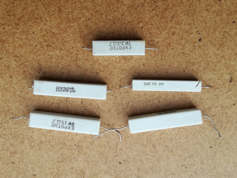 |
| Fig.18, We continue the restoration by studying the resistors, which are all wirewound with cement cases |
The resistors are from three different brands and have some assembly issues, to the extent that the 22 ohm resistor, which is too long (and probably non original), has bent leads underneath. Perhaps it would be best to replace them all, maybe with Intertechnik or Mundorf ones if we have space, or another good brand, but the owner will decide.
| our code (brand) |
stated value (ohm) |
type | resistance (ohm) |
power (watt) |
resistance (ohm) |
power (watt) |
| R1 Expotus |
15 | cement wirewound |
14.931 | 9 | 15.100 | 9 |
| R2a Intertechnik |
12 | cement wirewound |
11.996 | 10 | 12.051. | 10 |
| R2b Intertechnik |
12 | cement wirewound |
12.050 | 10 | 11.759 | 10 |
| R3b no brand |
22 | cement wirewound |
22.160 | 9 | 22.450 | 9 |
| R4 Expotus |
2.2 | cement wirewound |
2.153 | 5 | 2.202 | 5 |
See similar resistors, Expotus and Intertechnik.
For ohm measure we used the HP/Agilent 34401A multimeter.
Ceramic/cemented resistors like these are found throughout the TDL range but not on the early IMF models, which used different types (see the IMF Supercompact, better?). Let's see if we can use something better, too.
There's not much to say, except that capacitors certainly play an important role in the final sound of a Hi-Fi device, even if everyone exaggerates with adjectives and some manufacturers (who have mortgages to pay and boats to maintain) revel in prices that are completely out of control.
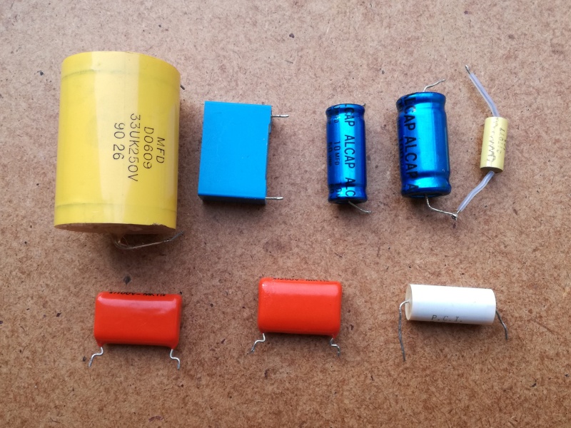 |
| Fig.19, The next step is to examine the capacitors originally installed. Unfortunately, we see five different brands with four different compositions. |
Throughout TDL's production, there has been continuous variation in capacitor brands and models, unlike IMF. Look at photos of C2 online; they are always different, even in terms of value. Which capacitors should be kept, and which should be changed, to avoid altering the speaker's tone? We will decide with the owner.
We only have two certainties regarding the capacitors: keep the large 33uF polypropylene one and replace the electrolytic ones. For the others, I need to discuss it with the owner, but I would look for other Philips MKT 2.2 and 3.3 uF ones to maintain sound uniformity.
Or .... to achieve better sound quality, replace all MKT capacitors with polypropylene capacitors that have a small casing. Electrolytic capacitors must remain and NOT be replaced with poly(something).
| our code (brand) |
stated value (uF) |
type | capacitance (uF) |
E.S.R. (ohm) |
V loss (%) |
Q factor (a.u.) |
capacitance (uF) |
E.S.R. (ohmt) |
V loss (%) |
Q factor (a.u.) |
| C1 Alcap |
100 | bipolar electrolytic |
108.2 | 0.08 | 0.8 | 18.4 | 98.6 | 0.09 | 0.4 | 18.1 |
| C2 MFD |
33 | DO609 metallised polypropylene |
33.95 | 0.02 | 0.1 | 328 | 33.98 | 0.01 | 0.1 | 517 |
| C3 no brand |
3.3 | MKT ?? | 3.22 | 0.12 | 0.1 | 396 | 3.32 | 0.09 | 0.1 | 477 |
| C4 P.C.I. |
2.2 | MKT? | 2.21 | 0.14 | 0.1 | 568 | 2.22 | 0.16 | 0.1 | 482 |
| C5 Philips |
4.7 | MKT | 4.84 | 0.06 | 0.1 | 552 | 4.84 | 0.06 | 0.1 | 475 |
| C6 Alcap |
10 | bipolar electrolytic |
11.19 | 0.38 | 1.4 | 39.4 | 10.07 | 0.44 | 1.6 | 36.3 |
| C7 Philips |
2.2 | MKT | 2.15 | 0..6 | 0.1 | 545 | 2.16 | 0.14 | 0.1 | 582 |
See similar capacitors: Alcap capacitor, P.C.I. capacitor, Philips MKT capacitor and MFD Capacitors (1991) Ltd.
For capacitance measure we used the Unaohm DC50E, for ESR, Vloss and Qfactor the Fnirsi LC1020E was used.
Given the excellent, incredible results obtained by measuring the original crossover components (aside from confirming our trust in Mr Fried), the decision to replace them is a POLITCAL CHOICE rather than a necessity.
It's a lot of work: selecting which components to replace, then choosing from the thousands available on the market, then purchasing them at a good price but also from reliable suppliers, and finally installing and fixing the components one by one.
Unfortunately, none of the sellers give us a penny for advertising them. In fact, I am reluctant to even mention the components used, as we do not receive a penny from these companies either. But perhaps it is better this way, as we are not pressured into recommending a capacitor just because they pay us.
And so we come to the point of irreversible choices that we try to justify:
But one of the yellow large capacitors is broken, and several inductors also need treatment!
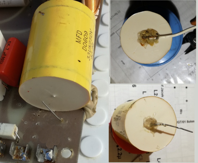 |
| Fig.20, It was fixed with a drop of silicone, and the travelling did not help. Since there is nothing to solder a new wire to, you need to use a Dremel with a carbide grinding wheel to dig out the white resin around the remaining wire to a depth of 1.5 mm. Then, solder a 1 mm solid core wire -across- it with SnPbAg alloy. Finally, cover everything with hot glue and glue the other rheophore as well |
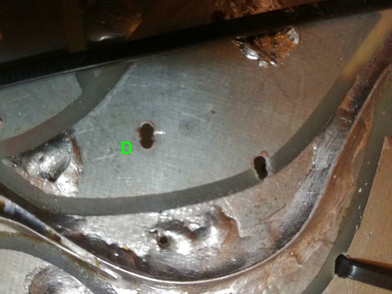
We have already seen in Fig. 9D how that inductor is ready to be unwound, but all the other inductors also need to be treated to secure the output wires before the wax bath.
 |
| Fig.21, we cannot use any solvent-based glue to secure the wires coming out of the coil because we do not know what type of varnish has been used on them. Therefore, we will apply a few drops of D3 or D4 vinyl glue and wait 24 hours before impregnation |
What did we buy?
Although every audiophile has an opinion on which brands and types of components to use, we have established three certainties: all resistors must be of the same brand/model, all capacitors must be of the same brand, and no components should be prohibitively expensive.
The field has now narrowed considerably. Below is a photo of what we purchased.
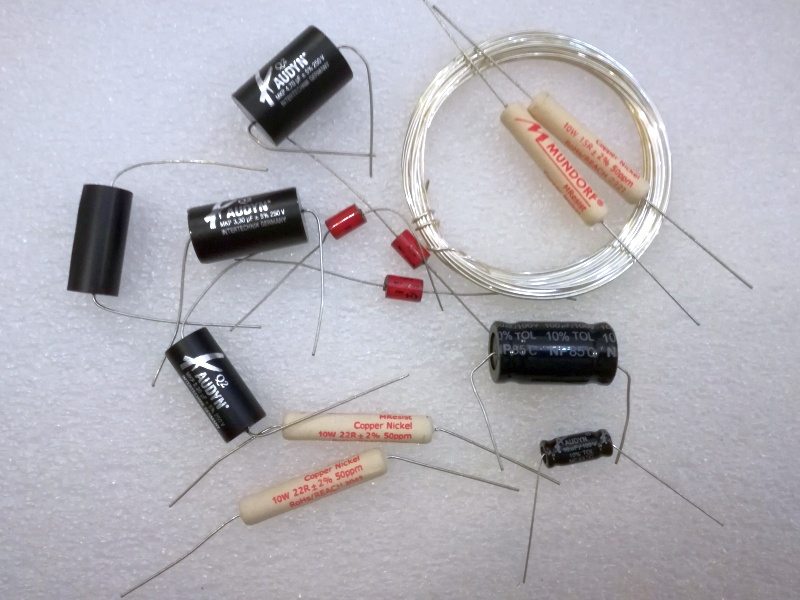 |
| Fig.22, Here is what we decided to install: at the top left, Intertechnik AudynCap Q2; at the top right, 1mm silver-plated 99.99% copper to reinforce the traces; at the bottom right, Intertechnik Audyn ELcap electrolytic capacitors; in the center, small bypass capacitors, AudynCap Q4 0.01uF; and we can also see all the Mundorf MResist resistors. The solder and fixing ties are not shown |
As usual, Banzai Music is missing a few components, so since we don't have all the 12-ohm Mundorf resistors, we can only assemble one of the crossovers for now. But the second shipment is free and their service is impeccable as always (and the components are genuine, not fake).
And here the polemic begins again. On the Internet, you can see videos of what they call the repair of a pair of TDL RSTL and TDL Monitor speakers that are modified without taking any measurements, with drivers thrown away and unlikely new ones purchased, with the crossover first having its wires cut and then worked on with a drill and reassembled without fixing the components.
aside from the despise shown towards components that have made history and that can function for another 10 years if reconditioned, paint the screws and reassemble them, perhaps in the half-stripped wood, instead of studying the PCB and the internal wires. That's what a real restoration is.
But the hundreds of views and enthusiastic comments tell us who is right and who is shouting in the desert.
Please let us dampen the vibrations
Can I copy here the the description before of fig.7?
Place your hand on a speaker playing music with energy at a high volume and you will feel the vibrations the crossover has experienced over years and years of music playback. I recommend Awakening by the Mahavishnu Orchestra or Thunderstruck by AC/DC for this test.
That is, each component must be protected from vibration with some kind of individual system, and then they must all be secured to the PCB or wooden base, which must then be securely attached to the cabinet structure. Of course, if the crossover were external and connected with 1/2 meter of ultraflex wires, that would be better.
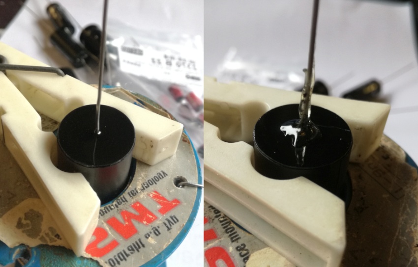 |
| Fig.23, hot glue, easy to assemble and durable. On the left is the original capacitor, on the right is the capacitor after the work, where we can see the pyramid of glue that secures the conductor. |
The operation is repeated on ALL newly purchased capacitors, with some difficulty as in the case below.
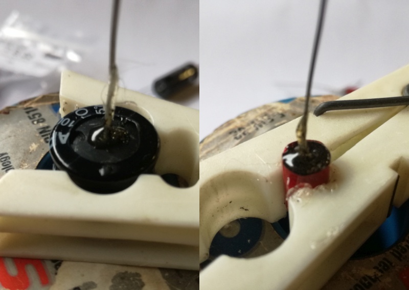 |
| Fig.24, on the left is one of the electrolytic capacitors. When applying the glue, be careful NOT to close the vent hole. On the right is the small bypass, which should be heated as little as possible, even if too much glue is applied, but quickly. |
Hot glue also has another secondary but very important function. The components will then be soldered onto the printed circuit board, turrets, flying wires, etc. If the glue melts during soldering, you have used too high a temperature and/or the soldering iron has been in contact for too long.
Right, let's move on to assembly ..... but not just yet. Does anyone know what we mean when we talk about outer-foil? Surely those who pretend to repair speakers know what it is.
Audiophiles have begun to understand that the position of capacitors in the circuit is important, and we hope that designers are also aware of this.
Unfortunately, our study of measurement methods has led us to some unpleasant conclusions about the use of capacitors and has caused us to re-evaluate Russian PIOs, Sprauge Vitamin Qs, Jensen TJS and Italian Ducati and Inco, that is to say, those with metal cases.
Once the inductors have been fixed as shown in fig. 17, we can move on to solving the problem of tracks that are too thin on the PCB. We discussed this problem on a previous page.
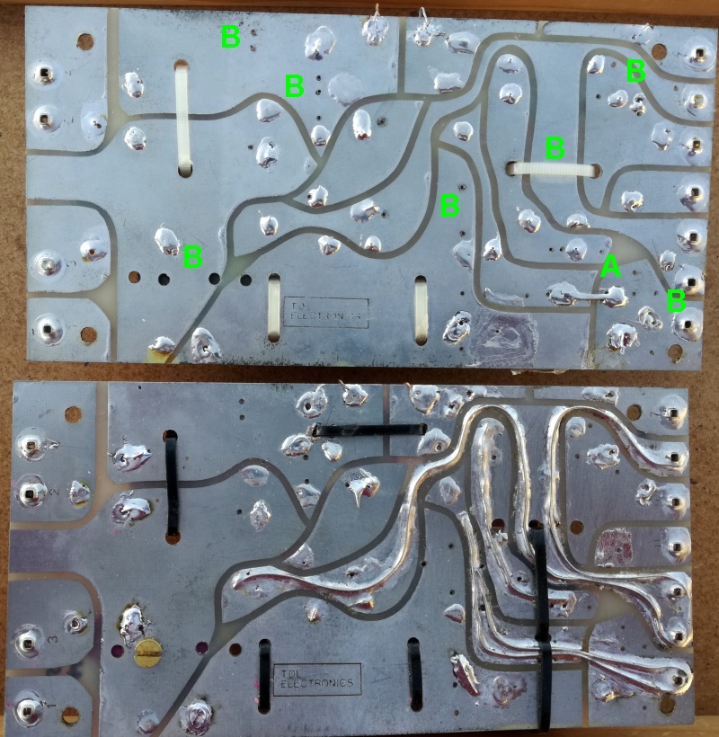 |
| Fig.25, the original PCB is at the top and the result after thickening the tracks, which were too thin, is at the bottom. We used 1 mm diameter wire (Fig. 22) and 60/40 solder (note the existing bridge in A, which modifies the crossover structure by connecting C5 (4.7 µF) directly to the high input) |
Fig. 25 also shows the brass bolt head that secures the inductance at the bottom left. At the top, in B, are all the existing holes, as shown in Fig. 11. We can use these to reposition our new components.
Other parts of the PCB could be reinforced with 1 mm wire. However, we will use the wires from the new components for this purpose. We will bend and solder them without ever cutting them. See below.
Sorry, but seeing this type of cable used between amplifiers and speakers (and you see them at Hi-Fi exhibitions and maybe even at XY's house) and seeing the PCBs of many crossovers encourages us to reinforce the tracks by any reasonable means.
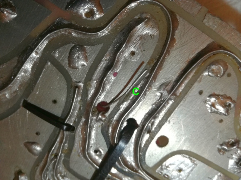 |
| Fig.26, our new components have high-quality copper wires of an appropriate diameter. Rather than cutting them, we bend them where necessary to reinforce the tracks, as shown in C (note the shadow of the flash) |
All capacitors and the pair of 12-ohm resistors are secured with new cable ties, but you have to make lots of holes!
 |
| Fig.27, the cable ties are 100 mm long and 2.5 x 0.9 mm thick, so we need to drill 2.5 mm diameter holes. However, to avoid weakening the thin PCB, we use a Dremel and a diamond cutter to make slots measuring 2.5 x 1.0 mm instead, as shown in D |
Let's look at two examples of fastening with cable ties, first the non-polarised electrolytic capacitor of the woofer.
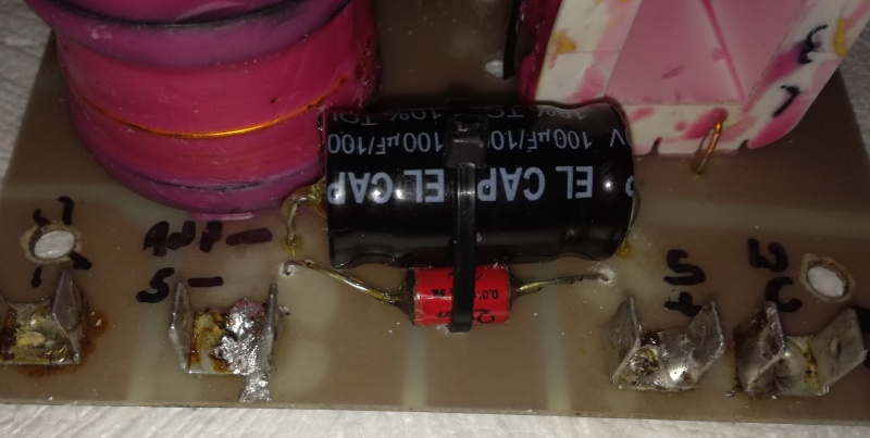 |
| Fig.28, fastening with a cable ties of the 100uF capacitor with its 0.01uF bypass |
And then we'll see how to attach the large 33uF polypropylene midrange capacitor.
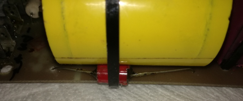 |
| Fig.29, fixing with a cable ties of the large 33uF polypropylene capacitor with its 0.01uF bypass |
And finally we see the complete crossover.
 |
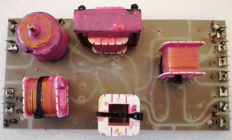
| Fig.30, here is the finished crossover without the wax coating, which we will see later on. Wires and labels have been added to make assembly easier. The original high-resolution photo is attached |
As shown in Fig. 30, the crossover weighs 1,050 grams and is secured by just four wood screws at the corners. To reduce vibrations, it would be better to find another fixing point.
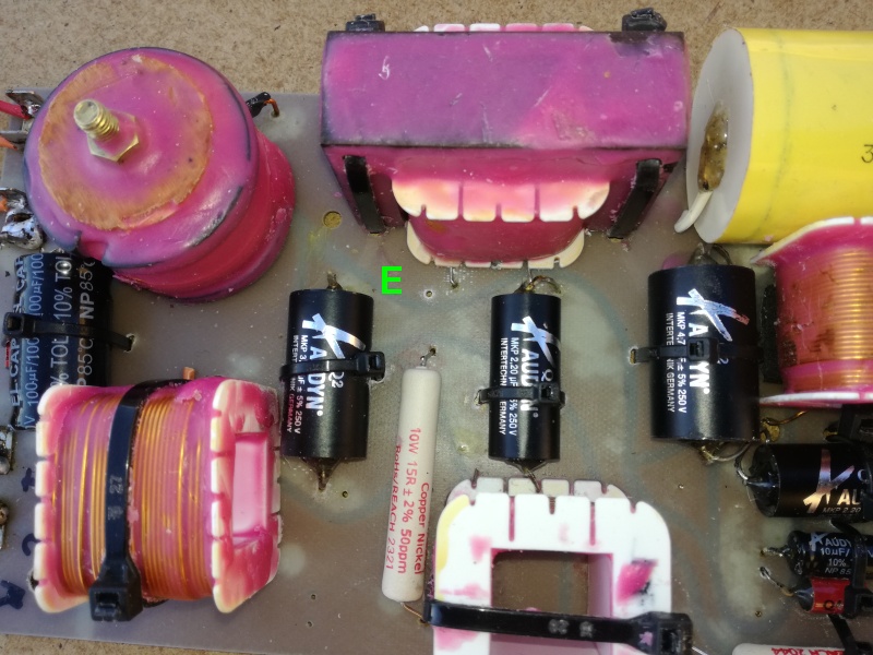 |
| Fig.31, we can also see, in E, a new hole near the large, heavy inductors L6 and L2. Enlarging it will allow you the owner to use a 3 mm wood screw, which should be more than enough to stabilise the centre of the crossover |
Let's look at the crossover from the soldering side. A lot has been done to increase the conductor cross-section between the components. Perhaps even a point-to-point connection would not achieve this result.
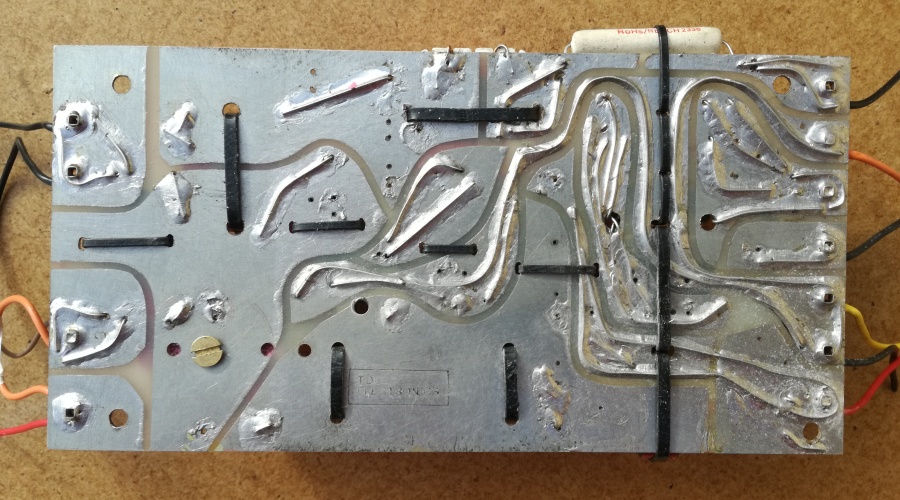 |
| Fig.32, the welded side, cleaned of rosin and ready for immersion finishing |
If we zoom in on the photo, we can see a detail that we have tried to reproduce in all the welds.
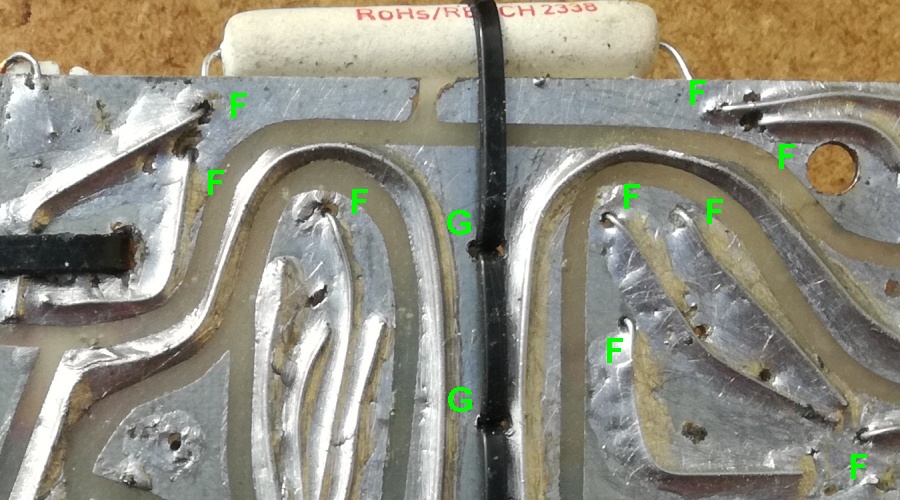 |
| Fig.33, the solder joints secure the wire without reaching the holes in the PCB, which reduces component heating during soldering (F). Furthermore, slots are used instead of large holes for passing the cable ties through (G) |
To finish the job, we need to immerse everything in a wax bath. Be careful to keep the temperature just above the wax's melting point. AudynCap capacitors are rated at 85°C. This will secure all the components.
 |
| Fig.34, the crossover ready for shipment, see also the high-resolution photo |
Once the work is complete, the owner, Jacek, will need to fix the crossover inside the cabinet. Once again, we are trying to reduce the vibrations induced by the cabinet towards the crossover.
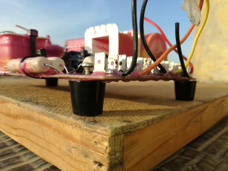 |
| Fig.35, The TDLs in the Monitor series usually have the crossover fixed above the pyramid-shaped foam layer with screws that need to be tightened to a certain point? However, when using rubber grommets as shown in the photo, the screws can be tightened properly but the connection remains dampened |
The rubber pads must be made of a soft rubber that can be squeezed with your fingers, but not so soft that they collapse under the screws.
Even if you take great care when assembling the components, having to reposition them to make space and add bypasses can lead to mistakes, but a couple of measurements help you understand if you are on the right track. Of course, one of the crossovers (fig.10) has remained intact until now!
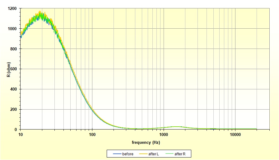 |
| Fig.36, Impedance graph of the high section of the crossover in Fig. 10 (before) and the crossover in Fig. 30 (after) by installing two 8-ohm resistors in place of the mid/high drivers for left and right Xover. Use the mouse-over feature for a better comparison of the charts using zoom |
We were interested in the overlap of the curves to confirm that we had not altered the crossover. We also observed the trend of the mid/high section, which has a very high impedance in the low frequency range and gradually decreases to a minimum at around 450 Hz et 20,000 Hz.
How a crossover works and how its components behave, in theory and in practice. Feel free to skip this section, as you already know all about it. In fact, explain it to the other dummies who are listening to you.
But if you want to know more, here are some links:
This page is already too long, and repairing the tweeter first requires various measurements, an attempt at repair, and then repeating the measurements to study the result.
We need to write a new page dedicated solely to repairing a tweeter dome.
Below are the files mentioned on this page and available for download:
| In the last years at Universita' Degli Studi di Roma La Sapienza |
Dr. G. Visco already contract professor for Chemistry in Environment & Cultural Heritage into ---------> |
Laurea Degree Course of Sciences Applied to Cultural Heritage for Diagnostic and for Conservation |