| read the Warning | read the Discalimer | the brand History | more and more Information | the TL/12+ & schematics |
| why here, The problem | what Inside | the Fault | Repair it | final Test |
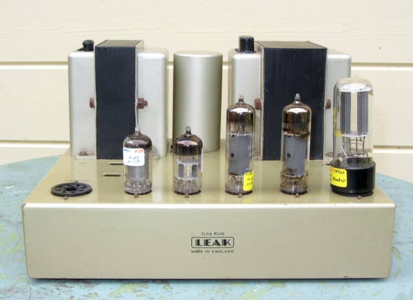 |
| Fig.1, from the Mullardantiques website a Leak TL/12 plus completely original both outside and inside, very hard to find. Here are the original, large, photos, the case and the internal board. |
Warning! If you are not familiar with electronics, do not attempt to open/repair!
After 2 hours from switch off you can suffer a fatal electrical shock
PRIMA di continuare a leggere queste sono le istruzioni.
please open this one BEFORE start reading
All trademarks mentioned and links are presented here for informational purposes only and to confirm statements made by the author. The author of these pages DOES NOT receive any remuneration from the mentioned brands and the listed links.
In any case if you decide to use the suggestions on this page you do so at your own risk. Repairing electronic equipments, even just opening it, can put your life at risk, so don't do it.
If you do not accept and/or not understand the statements in this disclaimer, written in blue, exit this page immediately.
Everything exposed in this web page is only a suggestion, probably you won't obtain the aim from you prefixed following it.
A true collector is looking for a) original items without any replaced parts, b) or if a Critical Restoration has been done that it is possible to go back to the original version. Lacking the previous 2 statements the object (not only for me) has a value of zero euros.
Yet another company founded by a single person, Harold Joseph Leak (1907-1989), who established H. J. Leak & Co Ltd in 1934. As always, someone was needed to actually design the circuits and plan the equipment, Ted Ashley, who remained with the company until the 1960s (a pattern already seen at Marantz, Hewlett Packard, Apple, Rolls Royce, Commodore, etc.).
H.J. Leak became famous for his first amplifier and his obsession with harmonic distortion. In fact, its first amplifier, the Leak Type 15, boasts the inscription "Point One Amplifier" as it claimed 0.1% THD (which was quite a feat to measure at the time!), KT66, 15W, and it was 1945.
His justified obsession with reducing THD clashed with the limitations of the time, so that 0.1% THD measured today is true, but only up to 0.5W, after which it rises and rises. But Nelson Pass founded a brand called FirstWatt, reminding us that we usually listen at these power levels if we use real loudspeakers rather than boxes with a hole in them.
Today, few are sold, and in 1948, by cutting costs and some technical sophistication, the wattage was reduced to 12W with the Point One TL/12, which became a commercial success.
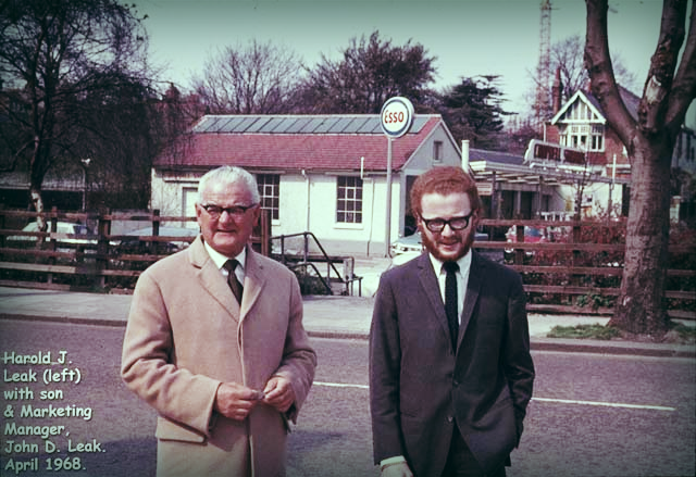 |
| Fig.2, Harold Joseph Leak and the son John D. Leak |
You may still find an auction online for a Leak TL/12 Point One in pristine condition for a few more months, but for €4,219, as a collectible item.
The TL/12 minus & TL/12 schematics
The TL/12 amplifier is a huge commercial success, but as usual, greed gets the better of people, so someone decides to build a similar one that costs much less to manufacture and a little less to buy. The marketing department then looks for a name ..... let's add a + to the name, so it looks like an improved version.
There are so many simplifications that it would be long and misleading to discuss them, but anyone who understands a little about tube amplifier electronics can compare the two diagrams below.
Fortunately, the publisher Howard W. Sams & Co Inc of Indianapolis published the wonderful Photofact Folders, with diagrams, voltages and component lists that are often not even found in service manuals.
Below are diagrams, which differ slightly from each other, reviews and news about the two TL/12s that are not easy to find on the internet:
The real TL/12 (not the TL12+) is one of the few tube amplifiers with negative feedback that must, CORRECTLY, be varied according to the speakers, i.e. the load (see R23 of Fisher 80-AZ). You can't do without it (but 1000 other amps do) if you take the negative feedback from the secondary winding.
Some great designers use a special winding for negative feedback, such as Marantz 8b, Marantz 9, Marantz 5, McIntosh MC30, McIntosh MC60, Lundahl LL3733, turning a simple amplifier into a legend.
Ma perche' me lo hanno portato?
No one likes to see a GZ34 rectifier burn out, but when the right amplifier burns out another one and then eats up a rare Mullard, then there's a problem.
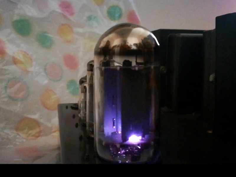 |
| Fig.3, Extracting a frame from a video made specifically to look for a fault that is difficult to reproduce, here is the moment we are interested in (the valve was saved by a 100mA fuse on the anode) |
If you are interested, here is the entire video, .AVI, 11.2 MBytes, with two important moments at 0:06 during warm-up and at 0:13 when the aforementioned fuse blows. Given the diagram seen previously and this video, let's do the usual theoretical and then practical analysis.
After measuring the voltages without the valve, OK, and given the above, it seems that it is the first capacitor that is eating up the valve.
The TL/12 minus that was brought to me has already been updated, so let's open it up and see what we find.
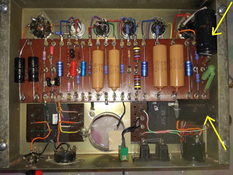 |
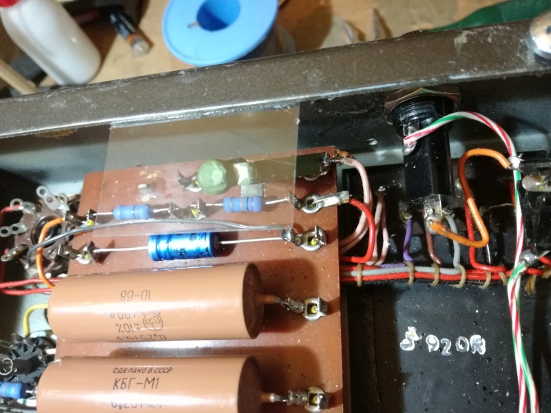
| Fig.4, Let's remove the bottom cover and analyse the update work carried out. Here is the high-resolution photo |
No negative comments on the upgrade work, which in any case uses excellent Russian PIO capacitors (even if some criticise their use as coupling). We note, however, that capacitors C13 and C14 are new but soldered in a strange position.
Repair already done, we replace C14 with a new capacitor and with a new valve it plays for 2 hours straight.
But this is NOT a solution, it's a botched job.
The fault is not the burnt valve or the leaking capacitor, it is the layout.
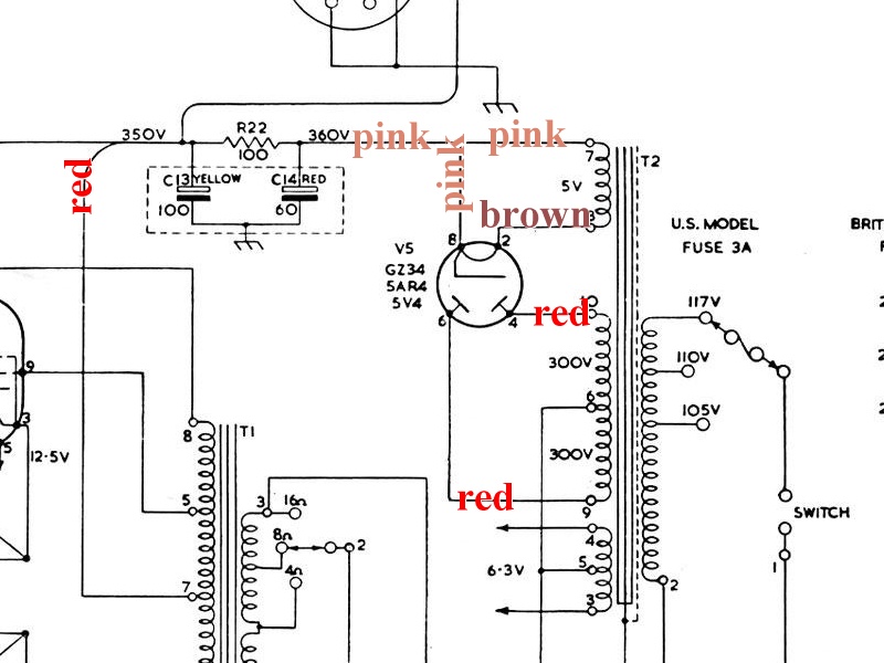 |
| Fig.5, in this diagram, we show the colours of the wires between the transformer, GZ34 and multiple capacitor C13-C14 |
The multiple capacitor is far from the rectifier; in fact, as we can see below, the salami-style binding of the wires originally lengthened the path even further.
Furthermore, capacitors from 60 years ago had very different characteristics from those of today. For example, they had a much higher ESR, so much so that, without knowing it, some people replace them anyway, thinking they are faulty.
There is a lot to say about old capacitors that create the sound, magic and euphony of old amplifiers and preamplifiers, how to measure them, how to test them at rated voltage and how to regenerate them. You could read something by Pearl-Hifi or from Rodney Champness.
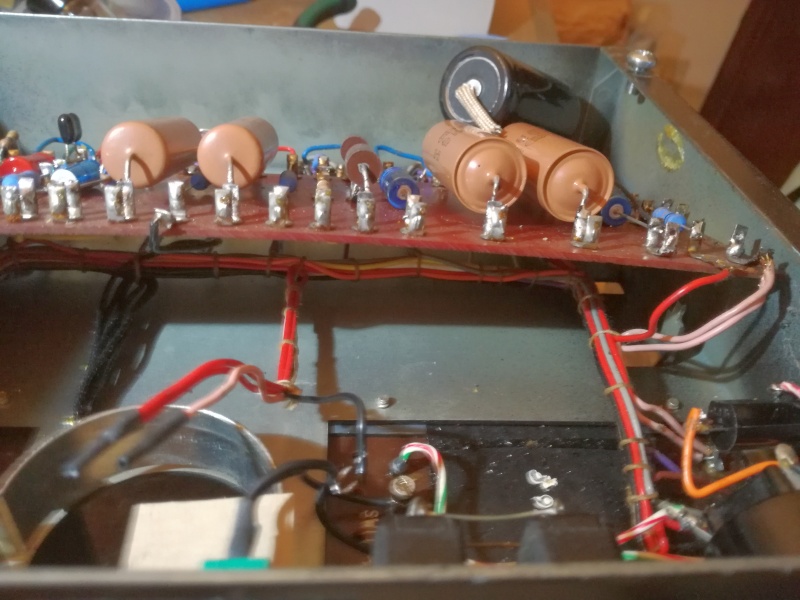 |
| Fig.6, let's lift up the main board and see the long path of the red and pink wires already seen on the diagram |
The moment of ignition is one of the most delicate for the rectifier valve, which is working on what is almost a short circuit that requires a lot of current while it is still heating up. The datasheets of the major manufacturers explained clearly to designers what to do, see fig. 7 below. Wind the transformer to obtain the right series resistances, or add two small Rs before the anodes.
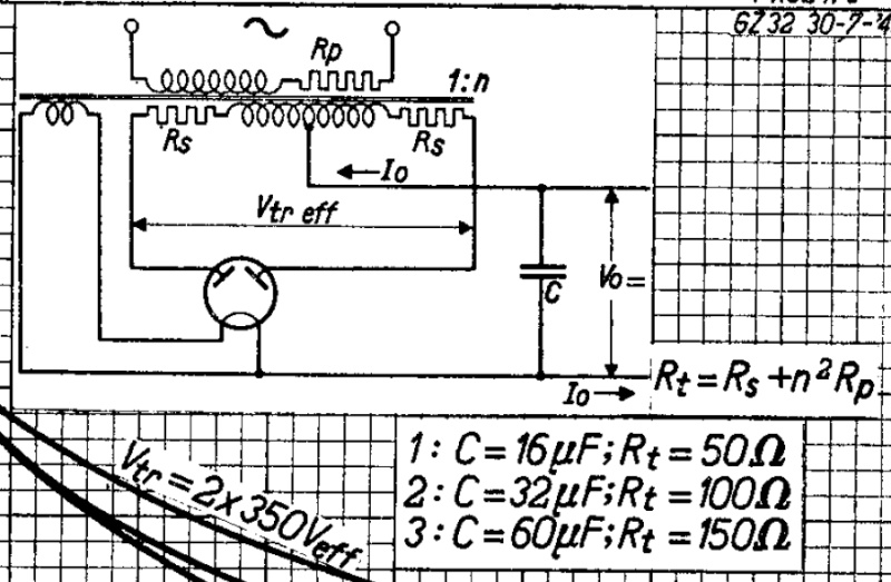 |
| Fig.7, from the Philips datasheet for the GZ32, dated 1949, we can see how the filter circuit with capacitor input should be constructed |
Mr. Ashley knew this well and in fact placed the two capacitors C13 and C14 far from the rectifier but close to the output transformer where current is needed, but whoever made the modifications did the opposite.
At this point, the repair is simple: we empty the double capacitor, choose a pair of high-quality capacitors, and with a few solder joints and some good wire, we rebuild the double capacitor.
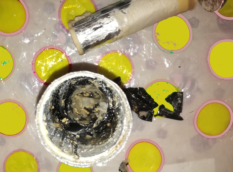 |
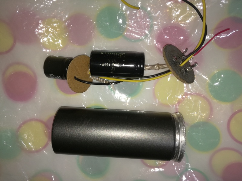
| Fig.8, easier said than done, the cardboard cap comes off with some difficulty, but the tar on the bottom is not easy to remove. Everyone has their own method for not damaging the lettering and exterior paint of the old condenser |
Care must be taken with the internal insulation of the old capacitor (previously, see fig. 8, the armouring was held in place in the centre by tar on the bottom and by cardboard contacts). We use a rolled-up sheet of cardboard.
 |
| Fig.9, to fill the gap, we use rolled-up cardboard; some people use wax, others use tar, but be careful with the maximum temperature of the new capacitors. |
Fortunately, whoever made the modifications did a good job and didn't cut the original cables, so we can close the double capacitor with its contact card, reassemble it, and solder the wires according to their colors.
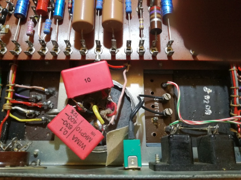 |
| Fig.10, once the dual cap was reinstalled, the owner rightly asked to add 0.1uF in parallel to C13 and C14, which was an excellent idea. We chose Wima MKP10, the best of this brand, and went generous with the voltage. The high-resolution photo shows the good work done by those who made the modifications. Note the soldering, fastening, and cutting of the components |
Fig. 10 allows us to praise those who made the modification (apart from that blunder on the position of C13 and C14), good soldering without residue, good cuts, etc. ... but that red resistor is so stuck.
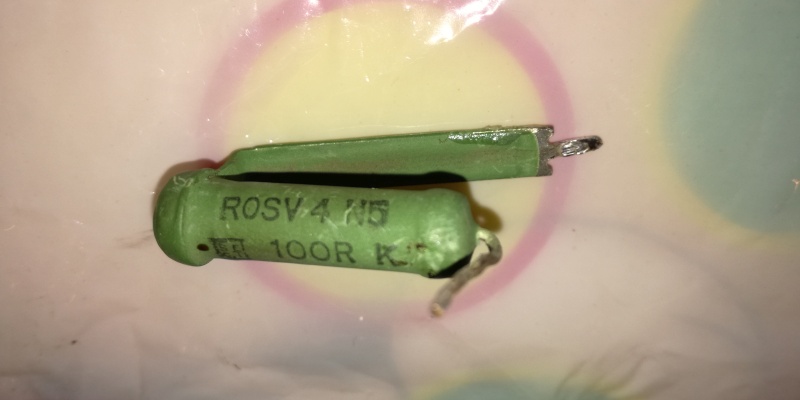 |
| Fig.11, the original R22, shown on the right in Fig. 4, is a SECI type ROSV 4, 100 ohms, 5W wirewound |
Wire-wound resistors should not be used in crossover high-pass filters due to their parasitic inductive component. Here, however, if there were an inductive component, it would greatly aid filtering.
I have a distant memory of when, as a young man, I was asked to repair a 40W tube cinema amplifier with a similar C-R-C circuit, but the R was a large, long resistor with wire wound around a ceramic tube and a nail stuck in the tube held in place by a kind of resin. It seemed original, the R was fine, and I didn't change it, but I wondered for years what they had done until I discovered that they had built a rudimentary inductor that certainly filtered better than the R alone-geniuses of yesteryear.
 |
| Fig.12, and here is the R22 installed, and we also insulate the area from the metal bottom cover |
With the installation of this last component, we should have completed the repair.
There is little to photograph in the final test, let's see how it was done:
But really measuring old amplifiers can lead to a lot of disappointment when compared to a Yamaha B2 from the 1970s, a Myst from the 1980s or a Pioneer M-90 from the 1990s.
| In the last years at Universita' Degli Studi di Roma La Sapienza |
Dr. G. Visco already contract professor for Chemistry in Environment & Cultural Heritage into --> |
Corso di Laurea in: Scienze Applicate ai Beni Culturali ed alla Diagnostica per la loro Conservazione |