| read the discalimer | the history | what model ? | standing or? | the midrange |
| the mid chamber | mid impedance | mid without surround | the tweeter | the woofer |
| the crossover | crossover repair | loudspeaker measure | download files | . |
All trademarks mentioned and links are presented here for informational purposes only and to confirm statements made by the author. The author of these pages DOES NOT receive any remuneration from the mentioned brands and the listed links.
In any case if you decide to use the suggestions on this page you do so at your own risk. Repairing electronic equipments, even just opening it, can put your life at risk, so don't do it.
If you do not accept and/or not understand the statements in this disclaimer, written in blue, exit this page immediately.
Everything exposed in this web page is only a suggestion, probably you won't obtain the aim from you prefixed following it.
A true collector is looking for a) original items without any replaced parts, b) or if a Critical Restoration has been done that it is possible to go back to the original version. Lacking the previous 2 statements the object (not only for me) has a value of zero euros.
Be very careful when buying a vintage, antique or historic loudspeaker. After 40 or 50 years, the magnets suffer from demagnetisation and the neoprene suspensions are now a wooden ring, the plissé and impregnated silk has opened up in the folds, and the foam, now sticky like bitumen, will drive the repairer crazy.
And the worst is yet to come: oversized broken coils, oval or square suspensions that are impossible to find, cardboard cones with impossible angles. And there is no cure for everything.
Beautiful speakers, with captivating sound when new, but a proper restoration can cost much more than the car itself, as in the case of this Fiat 500B.
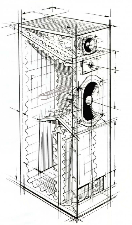
On the right the drawing of TDL Monitor Studio 4, similar to TDL Monitor Compact, with more robust enclosure compared to 4 way TDL Monitor
IMF and TDL are linked under the same idea of speaker, the Transmission Line, around this idea in UK work some of best speaker designer as Irving M. Fried, John Stuart Wright, Jim Thiel, Andy Lockwood. After the work of those expert what do you aspect on sound quality and accuracy?
The old address is "TDL transducer, Transducer Development Ltd, High Wycombe, Bucks, tel (0494) 35576". Today exist a web site in UK but seems to be frizzed.
Can I rewrite all of TDL and IMF history here? Probably is best present links available at august 2023, see below:
BE CAREFULL, the drawing and ALL photos are under copyright and you have NOT right to use without written authorisation from me. The drawing came from a work of my fried architects using an old draw from a TDL leaflet.
The history of speaker production, first in USA with the name I.M.F., after in U.K,, more with coworking with Elac, someone speaking of a litigation and born of TDL brand (with some speakers build in Germany), more production in USA with poor speaker, and so on.
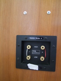
Fortunately this one have the original binding post, see photo, and serial number with L and R mark. Please if you have those binding post DO NOT change, those are better of your new and expensive.
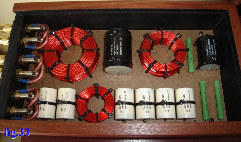
Above the binding post and socket of this TDL we can see the four inox pass through screws fixing the mid-high-pass part of crossover in place of the poor wood screws from inside (the large photo is here)
The original xover is large and "high" and put in the inner port of the transmission line tube, not a good position, see the drawing above.
So the original PCB board of crossover (marked TDL Electronics) was cut in two parts, one with bass-pass put in the original position, and the mid-high-pass put over the binding post, practically under the internal box for midrange speaker.
A similar model, called TDL Monitor Compact, was produced by Germany distributor of TDL, see those 3 pages of the leaflet of A.O.S. Ascot speaker, page1, page2, page3.
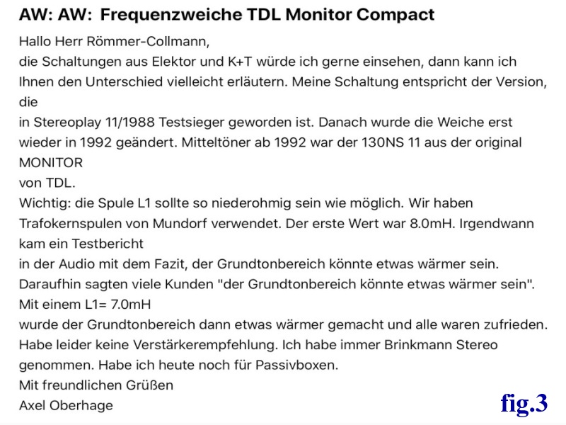 |
| Axel actively participates in many forums where loudspeakers are discussed. Here is one of his posts on the old-fidelity-forum.de/thread-39096.html. |
Here you can find the translation and some other message from Axel.
The RSTL, the Monitor, the Studio 4, all the RTL are floor-standing speakers, but you have to ask yourself "how" to place them on the floor.
Browsing through blogs and forums, the answer is already there, On The Spikes. Unfortunately, in this world of adult toys, all you need to do is find someone who speaks well, loudly, who says something ridiculous, and after a few posts on forums, it becomes law. How sad.
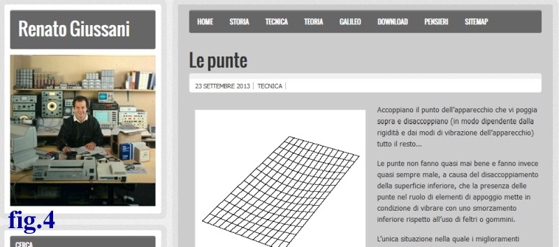 |
| The legendary Renato Giussani tells us something about the trend of the spikes. |
One of Italy's most famous loudspeaker designers wrote about technology on his website. In September 2013, he wrote something about spikes, effectively killing them off: "Le punte non fanno quasi mai bene e fanno invece quasi sempre male, a causa del disaccoppiamento della superficie inferiore, che la presenza delle punte nel ruolo di elementi di appoggio ...". Here is the original page. We thank his son for keeping the content online.
How should one of the TDLs in the monitor series end? With a base into which the case fits. If you look underneath, you can see a step that is designed to fit into its base, but this was optional!
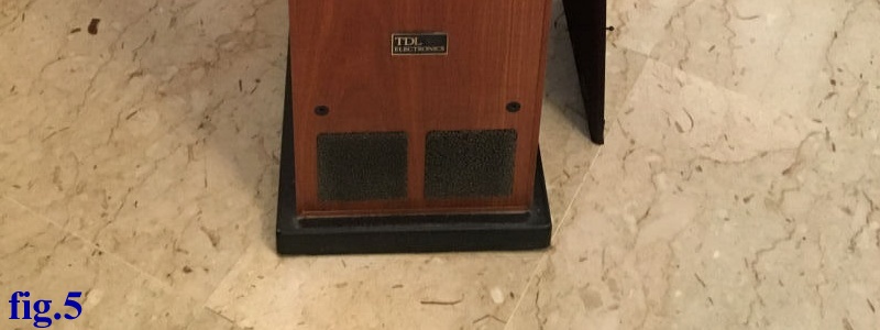 |
| Let's look at the base, often black, under a Studio 4. The base is slightly wider to give stability to the cabinet. |
But if we don't put the tips on, what goes underneath? We simply follow what is done to insulate an air compressor, a large motor, or a car engine from its chassis. Or follow the suggestion of Mike Fitzpatrick of LiquidAudio restoring a B&W Nautilus 803, I've also selected and installed some really excellent new hard rubber feet; these make a big difference to stability and sound.
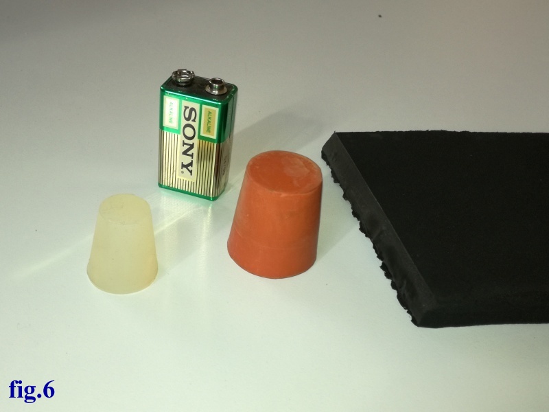 |
| From left: a silicone stopper, a rubber stopper, a strip of material similar to Sorbothane © but much less expensive. Tip: Do not use shims that are thicker than 20-25 mm. This way, if one of the shims slips, the box will bend to one side, but it will not tip over. |
The stoppers can be found in oenology shops or from chemistry laboratory suppliers. There are various alternatives to Sorbothane ©, so make sure you do your research.
But there is one rule. The material must COMPRESS SLIGHTLY, like a spring. Therefore, the support surface must be sized so that when the box is placed on top, the material yields by about 1 mm.
And now let's analyse the drivers one by one.
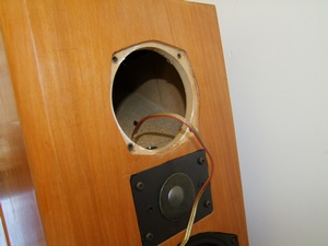
As show in the drawing the midrange have a small box build as a pyramid on the top of the speaker filled with 2 different wool.
The fixing of speakers is one other mystery. See a zoom of the photo the midrange, and all other components, was fixed with Captive T nuts but with M4 screw not whitworth, also the head of the screw use the Brugola metric to fix it.
In photo we can see also the internal cable, a QED crystal type, 1.5mm2 section.
An accurate lecture of the photo show the quality of the wood used. Really is not a wood but a high density MDF and the very thin placage de bois as ready to detach glue or not.
If the midrange is damaged, it must be repaired, not replaced. The coil is to be found, as are the spider and the suspension.
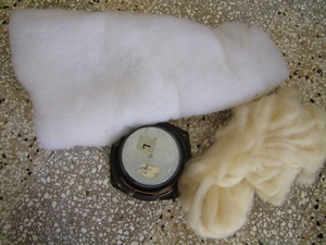
The midrange has a separate box. Measure the volume of this is about 9 litres and it is filled with 2 different wools.
See on the left, the white material stay on the cuneiform section of the box, the yellow part stay behind the speaker. The large photo is here
Jerry Bloomfield in 2011 produced a list af Elac speaker used by IMF and TDL, we can find here here, but I suppose there is almost one error, for this midrange as example. Jerry list this values:
Model: 130NS 13, Size mm: 131, Depth mm: 70, Coil mm: 25, Surround: rubber, Cone: polypropylene, Frequency: 250-4000, Cont. power W: 40, Amp. power W: 150, Resistance ohm: 7.40, Impendence ohm: 8, Mechanical Qm: 1.80, Electrical Qe: 0.48, Total Qt: 0.38, Equivalent volume Vas: 11.6, Resonant Fs at Hz: 52, Sensitivity dB: 84.5. The large photo of my is here
What's is the differences in impedance and phase in a speaker running with and without the surround? The rubber of 130NS 13 is dead, all the surface have cracks and in some points there are detach with frame, see photo. The large photo is here
The new surround is similar in dimension to "EC-113A" but the rubber must be for midrange, not for mid-woofer. In Italy you must go to Trecastelli, near Ancona, to visit one of the best producer of foam, rubber, fabric for speakers (and spider, and dust cover, and ..), the OEB. But you can do a phone call if you live outside of Italy.
By restoring the first, I have a complete one and a disassembled midrange, from which an idea is born. How do the parameters of a speaker change according to the surrounding? For a first answer it would take; a midrange and 3 different suspensions, in foam, rubber, and fabric.
But we can start with this midrange, put the dust cover back on the one without suspension and do some measurements. Having a speaker without suspension you will need to make them work all 2 face up, with the magnet resting on a plane, indeed on several layers of thick rubber, and measuring only the electrical parameters in the air.
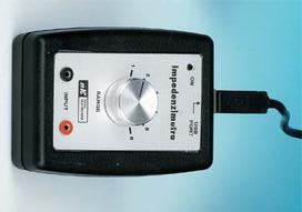
On the left the kit LX-1746 of defunct company Nuova Elettronica, kit LX-1746. This is an interesting complex measure instrument, with inside one audio card, one small amplifier and some calibrate resistors. All the work is done bye the software, from PhD. Alfredo Accattatis, today at Rome3 University. You can find description of Visual Analyser Project, and software at Sillanumsoft.org.
For calibration you must find some R, L, C with certified values "near" the values to be measured, almost 1% or better 0.5% of tolerance. Mouser, RS, TME, Distrelect have, but expensive.
Unfortunately the only really working version of the software, for me, is the 2011xe version. I test in 5 different computers from Win Xp to Win 8.1, from notebook to expensive desktop, but all the new version have problems and problems.
To compare the 2 speakers we can use the function to measure the impedance at various frequencies called "sweep function". This function produces an abnormal occupation of RAM so the spectrum must be divided into several parts, not too bad since using a 10Hz step to measure at 17410Hz, 17420Hz, 17430Hz doesn't make much sense.
When I started using this software I loved it, now I always discover new design-errors that are not solved, the Help is quite inexistent, no one manual (nor from users) is available, but only new and new UNDOCUMENTED functions are added. As example see this one.
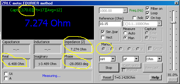 |
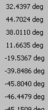
| the ZRLC windows of the Visual Analyser running sweep calibration, the manual setting is Z=impedance, see the yellow circles, upper the frequency, on the left the R value, in the middle the Z value, and down the Phase degree, please remember. |
Hit Capture auto in the window above the procedure of sweep, step by step, calibration start. When terminate we must connect the speaker and start the measure, see on the figure show the values at point 17 as 170Hz starting from 10Hz and with step of 10Hz.
When the sweep terminate we must hit the View captured button and obtain the following.
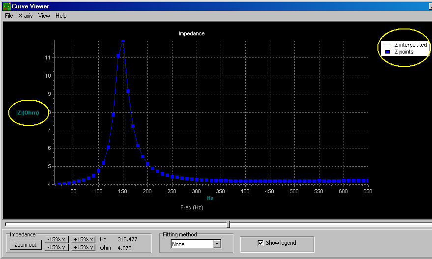 |
| This graph appears after hit the View captured button. Where are the other values? In the figure above we can see the resistance real value, the impedance value and the phase degree, necessary to describe a non-linear electrical device, as; Choke, Speaker, Snubber, Coil, and so on. |
As show in the first figure the software measure all of this necessary, essential, parameter (measure also Imaginary R value) and probably storage in the abnormal use of RAM, but do NOT SHOW. Without the software is a piece of junk, or a game for children, unfortunately.
130NS 13 with and without surround
With an incredible hard and complex work outside the capacity of almost all users we could obtain a table with the required measures. For ringworm I decided to try the operation instead of using another software that does it in minutes not days.
How you do it?
But do you realize that it takes a whole day of work and a lot of different software?
VA2011 is not bad, VA2021 is better, there are many functions but only one author has limits and after a while his creature gets out of hand, that's why the best open-source software is managed by a community, maybe only 5 users but each specializing in a task (program complexity grows until it exceeds the capability of the programmer who must maintain it; the 7th Murphy's computers law).
However after 2 days a good result is obtained, see below.
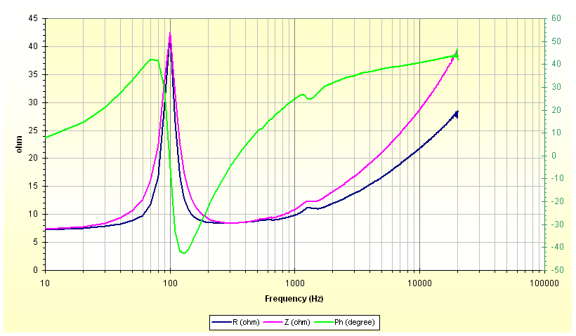 |
| The midrange 130NS 13 with new rubber, open air, face up, insulate from the table with rubber felt, after 2 days of work the curve obtained from VA2011 with NE LX.1746 kit. |
Thanks Mr. Irving M. Fried for choosing, this is a true midrange not a mid-sub sold yesterday and today as a wonderful speaker but that struggles to reproduce all the voice and instruments in this frequency range that makes the "timbre" of the speaker. Please compare this chart with your midrange chart!
I remember a similar design, a real Audax midrange, looking through the saved files I found the scan of a vintage catalogue, my file only says Audax-13cm, but it doesn't give the model.
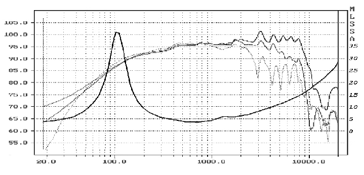 |
| An old, vintage Audax midrange, 8 ohm, 130 mm, 5 inches (obtained with old expensive, difficult to use, never update MLSSA hardware-software) |
We note the same dip at about 1200 Hz, about the same Z value at the resonance and also the same resonance frequency. But let's go back to the supposed difference between with and without surround.
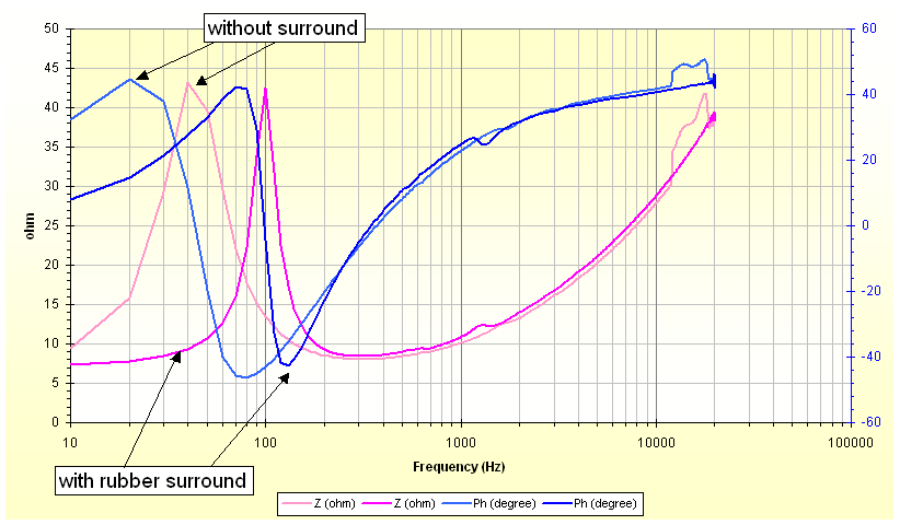 |
| 2 midrange 130NS 13 with and without rubber surround; all in open air, face up, insulate from the table with rubber felt Are evident some difference. |
Without surround the curve are "larger" the values are quite higher, the break-up of the cone is evident over 10KHz, but the dip at about 1200Hz disappear.
Soon if I find a real midrange (you need a mid since the Fr lowers a lot without suspension), to which you can mount 3 different surrounds I will repeat the measurement, but perhaps with another software like ..... good search.
If the 2 midrange are really dead I suggest replace they with JBL-2480 + JBL-2328 + JBL-2350, probably without xover modification :-) .
Having time I can spend other 2 full days to measure the 2 Woofers and the 2 Tweeters and design a chart similar to the above.
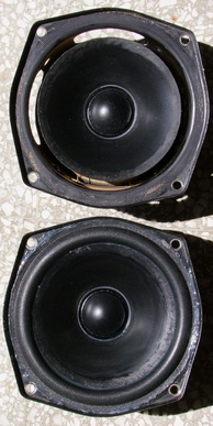
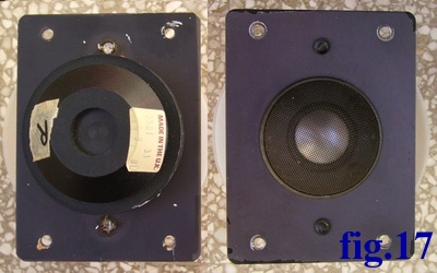
I find a spare time to measure the tweeter 25DT 31. On the left the photo of the tweeters. The large photo is here.
Reading from a previous cited list of Jerry Bloomfield we can show, Model: 25DT 31, Size mm: 120 X 90, Depth mm: 45, Coil mm: 25.4, Cone: aluminium, Cont. power W: 40, Amp. power W: 150, Resistance ohm: 6.8, Impendence ohm: 8, Resonant Fs at Hz: 750, Sensitivity dB: 87. The tweeter label is here.
If the tweeter is damaged, it must be repaired, not replaced. The entire coil, dome and former can be found.
We can see in photo a cover of tweeter, similar to a Mesh Tea Strainer, someone can think to preserve the speaker. I suppose this is a form of mechanical dumping in high frequency as often we can see with a piece of fabric under the dome.
I suppose this is a cut and reused tea strainer (after select the correct mesh), but it's probably a specially made piece of hardware.
 |
| A net covers the dome, why? To protect it from shocks, or to filter the emitted frequencies, or for some kind of damping. It was originally fixed with 4 glue points, but the magnetic field also holds it in place (it is supposed to be of soft iron then). |
The Internet has given voice to millions of idiots and incompetents who pontificate and discuss about things absolutely unknown to them. Their only habit is to show their ignorance and defend empty words spoken by them whose meaning they don't even know.
Why this outburst? In Italy there will be only 2 people, maybe 3, from whom I would accept advice on how to replace a woofer or tweeter. Let's name suggestion from Fabrizio Calabrese, from Sergio Canini, from the passed away Renato Giussani are accepted, from the other 1000 who write on the Internet I trust less than a bank note of 1 dollar of blue colour.
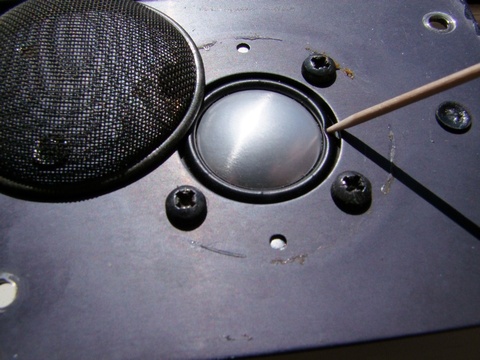 |
| The large photo is here. Replace this tweeter is not easy, see the rubber surround and the aluminium dome. |
If you replace the 25DT-31, see the rubber suspension, the dome, the rear small box covering the vented hole, you will certainly have some sound but not the one thought by Mr. Fried.
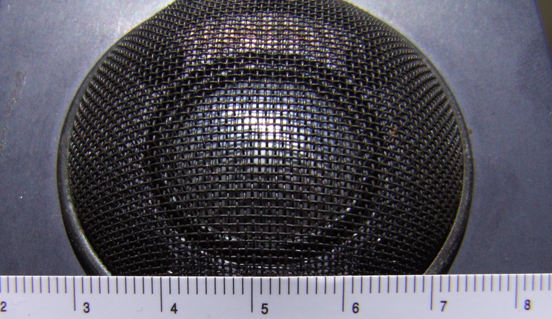
Can the mesh filter the high frequency? First we must measure the dimension of single mesh, see the photo with the tea-strainer fitted in place
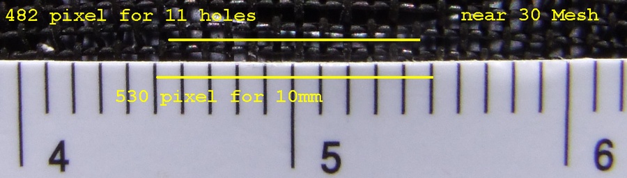 |
| Some measure, with aid of ImageJ, on the macrophoto of the tweeter's net. The hole have a square form with a wire diameter from 0.24 to 0.28mm and open light from 0.6 to 0.56 mm. |
The speed of sound is 331.3 m/s (STP), so with a simple calculation we can find the wavelength "similar" to the distance of the wire as lambda=394 KHz or similar to the open hole lambda=500 KHz. To obtain the diffraction at 10 KHz the wire distance must be 3.3 mm.
After another 2 days of work with VA2011 we can compare the impedance of the tweeter with and without the mesh dome, measured face up.
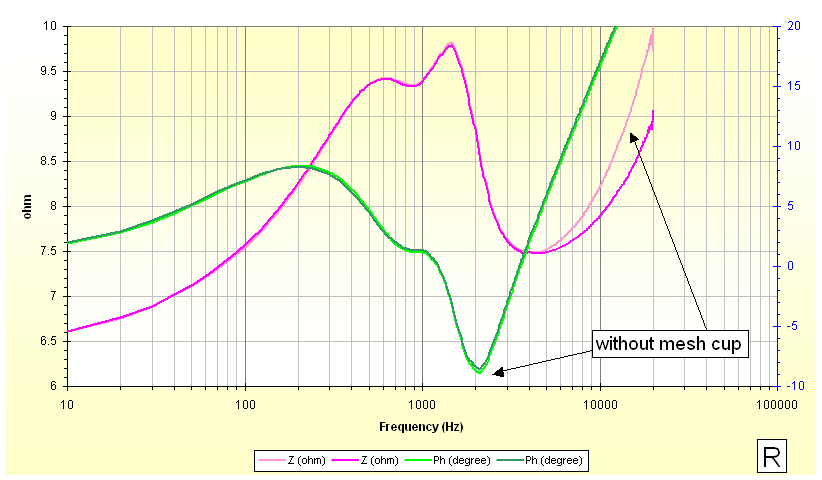 |
| The same tweeter is measured with and without the beautiful black dome shown above. As speculated, the genius Mr. I.M. Fried uses part of a net tea strainer to reduce impedance. Note that the Y scale is only 4 ohms wide. The two resonances near 1KHz suggest a high pass filter above 2KHz. Mouse over to see L tweeter. |
The left tweeter is more interesting, the naked tweeter has a break-up near 18KHz (probably a draft from the rear cover chamber) but with the mesh cup mounted disappears.
As we can see, the tweeters are quite different, but very similar (30 years old, but I would like to measure 2 new ones, sealed to control modern production). In any case, the effect of the mesh dome starts from almost 4900 Hz, "coincidentally" at a wavelength equal to the diameter of the dome.
The crossover frequency for 4-way TDL Monitors are 300, 3500, 13000Hz, according to the producer, and for Studio 4 and Monitor Studio they are 300, 3500Hz, exactly at the point of rising of the impedance Z.
If the 2 tweeters are really dead I suggest replace they with Mundorf AMT27D1.1, probably without xover modification :-) (so I contribute to stupid suggestions present in Internet).
Analizziamo il woofer e cerchiamo dei vecchi datasheet per fare un confronto almeno della curva di impedenza. Ma questa volta cerchiamo un altro software!/p>
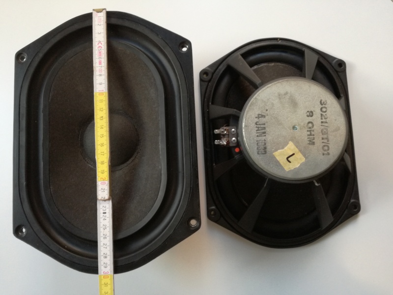 |
| The two woofer, 3021/GT/01, 8ohm, no brand, 4 january 1989. Really L=0.56mH, 7.2 ohm (DC measure), 2954 grams and R=0.61mH, 7.6 ohm, 2979 grams. Here there is the high-resolution version. |
After 40 years of use, there is a major problem that almost NO ONE mentions: demagnetisation. Alnico magnets suffer from this the most, but even ferrite magnets lose their magnetic field after 40 years. Measuring the magnetic field is difficult without original data (or a time machine to measure it at the factory), and there are perhaps only two laboratories in Italy that remagnetise magnets, so good luck.
But there is another problem with these woofers: the rubber suspension, possibly neoprene (for B139), which over the years (36) has lost its elasticity.
Let's move on to measuring impedance, but first let's run it in for 6 hours at 1W at a frequency of 50Hz.
Suspecting that there are problems with the woofers, we use a trick that I was taught many years ago: we connect the woofers in series and measure the impedance. We expect the curve to be single or at least almost overlapped, but instead ...
 |
| The impedance of the two woofers connected in concordant series shows two resonance peaks at approximately 58Hz and approximately 65Hz. Here there is the high-resolution version. |
This magnificent software, currently one of the best I have tried among the five mentioned by everyone, is no longer available. Its programmer, Ulrich Mueller from Wuppertal, Germany, probably did not receive adequate financial compensation, or perhaps he decided to focus solely on his real job in the audio field.
For future reference, we present the two impedance graphs and the .CSV files produced by the software (see Files). Someone skilled can use these to calculate the woofer parameters, but the software could also do this.
 |
| Please excuse the slightly different ohm scale, but here are the two impedance graphs: here the Left HiRes version, and here the Right HiRes version. More, in Files you can find the Left .CSV and Right .CSV produced by software. |
The specifications for the 3021/GT/01 woofer can be found, along with a page from TDL showing the curves, below.
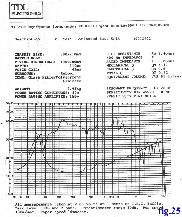 |
| This is the only page on the internet for this TDL woofer. |
What happened, what to do, let's at least try to clarify ideas a little. Please note that the shape of the woofer is similar to the B139/SP1044, but the specifications are quite different.
There is little to be done. If a new suspension cannot be found, regardless of the material, we will have to try to restore the one already installed. I will write a page specifically for this, remembering that there are preliminary steps to be taken (by a chemist specialising in the diagnosis in Environment the Cultural Heritage fields).
I buy this speaker about 4 years ago and promise me to restore/upgrade early! I already had other speakers, so I bought these out of curiosity about the IMF/TDL family, but it was immediately apparent that they needed some treatment.
But find time to dismount completely, find all necessary new components and rebuild is not so easy. Finally, in 2014, I find time to mount all previous obtained components as Mundorf E-Cap, Vishay resistor, Stannol Sn-Pb-Ag, inox screws, soft Pyramid Studio Foam and so on.
The crossover definitely needs some work, but it does NOT need to be butchered by geniuses, gurus, know-it-alls, pundits, smooth talkers or by by people who think they know everything.
If you would like to learn more about crossovers before continuing to read, please read Paul Apollonio's articles on Audioholics (more interesting the Editorial Note inside articles).
Let's start with the NECESSARY work.
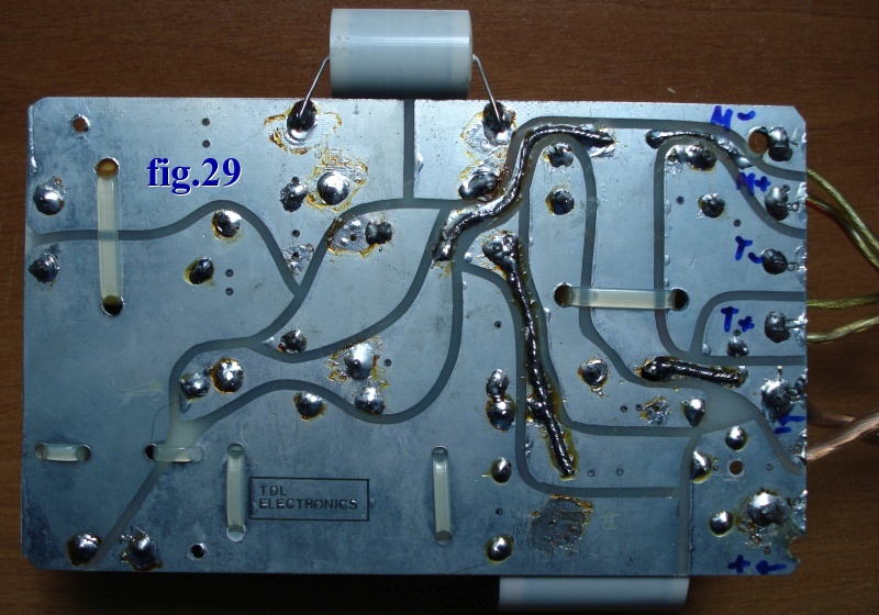
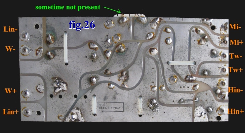 |
| The crossover on the soldering side is in perfect condition, as it has just been removed from the case. Here is the high-resolution version. |
The first step is to make some PCB paths thicker by soldering a 1mm solid core copper wire onto them. Be sure to use plenty of solder, but make sure you don't touch any of the other tracks.
The second step is to remove all the solder joints one by one with a desoldering gun, clean the area and then solder them again. Do each joint one at a time so that you don't drop the component.
What solder should you use? Definitely a reworking alloy, Sn60/Pb40 + rosin, or LMP HS10 Sn62Pb36Ag2 soldering alloy used for reworking in HiFi audiophiles (or similar but high quality).
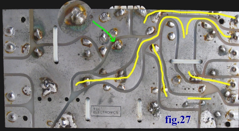 |
| In yellow, where the 1mm copper wire must pass to strengthen the tracks, as in the famous VTL Stereo 90/90 tube amplifier (1992), the green arrow shows a faulty solder joint. Here is the high-resolution version. |
The problem of PCB misuse and designers' lack of knowledge about the thicknesses and widths to be used has already been discussed on a my old web page.
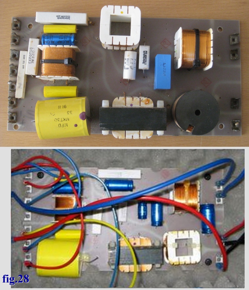 |
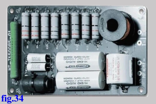
| What is the crossover of the Studio Monitor 4 and the Monitor Compact? These are two very different photos, but there are two other models, both with the same PCB! Look at the one above and see how many empty spaces there are on the PCB, as well as the many holes already drilled for another version, the one below is mine. Here is the high-resolution version. |
Next week I wrote other part of this page, but I can anticipate the crossover of my TDL Studio 4, the bottom of previous figure is mine.
Pay attention to the polarity of the wires when dismantling the crossover. There seem to be at least two versions: one with the tweeter in phase and one with the tweeter out of phase. Make sure to mark everything clearly.
How many speaker models did TDL produce? We don't know today because the catalogs only showed about half of the models produced (take a look at these!).
Your TDL Studio4, Monitor Compact, Monitor Studio4 will certainly have another crossover, perhaps the one described by Fortmont on the Stereonet forum. Here ther is a copy before it disappears.
Or perhaps you have another crossover like the one described by P.Seller in the audio blog Old Fidelity Forum, here is the link, and here is a copy of the schematic before it disappears.
 |
| This is my crossover after the upgrade. The woofer filter was cut away with a saw and a new board was constructed, anchored to the wood above the terminal box with inductance and capacitor. Note the reinforced tracks. Here there is the high-resolution version. |
Now we need to talk about the filter components, capacitors, resistors, inductors, etc.
We have two possibilities: 1) the crossover is working and shows no visible damage, 2) the crossover is damaged or one of the drivers is faulty (if someone use a Krell KSA300 to drive a LS3/5A and, of course, obtain this one, transformers, resistors, capacitors blow, driver flambee).
If the crossover is not damaged, you need to make sure that it has not already been destroyed by some idiot. Some photos of a similar one on the web may help.
In the first case, if you want to upgrade, you need to change as few components as possible. If we are talking about a Tannoy, a Kef, a Roger, an IMF, an MBL, an Ohm, a TDL, a Thiel, an Advent, an AR, a JBL, a Wilson, or a Klipsch, the designer was certainly not incompetent, but perhaps we can find some "cost saving" made during marketing that we can correct.
In the second case, a driver may have broken due to the failure of a crossover component, or the driver may have broken and taken another component with it. Or, if you are lucky, part of the crossover is broken but has not damaged the drivers (for now).
In both cases, certain rules should be followed in order NOT to distort/denature the speaker (unless that is precisely the desired effect).
But let's get back to the TDLs and, by extension, the IMFs, of which I restored 4 + 3 loudspeakers.
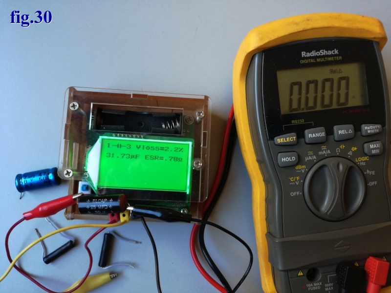 |
| An expensive and accurate RLC meter (U1733C ?) may not be necessary for a hobbyist who wants to work on his own crossovers. Perhaps an Arduino-based RLC meter such as the GM328A is sufficient, but... please check the accuracy of at least R and C with a quality meter. |
In the previous photo, a 25 uF 35V bipolarised ELCAP capacitor (from IMF crossover) measured with the RadioShack 22-812 meter shows 32.1 uF and with the GM328 shows 31.73 uF, but the latter also gives us the ESR and Vloss values.
PCB of crossover
The most expensive IMF and TDL series mount the crossover on a PCB board, while the more commercial ones have components soldered point-to-point on behind the input sockets (with other problems!). In the case of IMF, this is Bakelite or phenolic paper or phenolic cotton paper, which is easy to break and flammable. In the case of TDL, fiberglass with epoxy resin is used.
If the PCB is broken, like the one on an IMF that I repaired some time ago, it must be reinforced with two-components resins using a patch of the same type of material.
Almost all crossovers with PCBs suffer from the same problem: audiophiles buy a speaker cable from the famous AbcdefGhe brand for €3,000 per meter, unaware that inside it contains this:
 |
| Here's the usual problem: the crossover tracks are really too narrow and the copper is too thin. See the in+ that carries the signal from the amplifier and the lo+ that delivers it to the woofer. And let's also look at the track between in- and lo-. With mouse-over see the other side. |
However, with a soldering iron and some solid-core wire, following fig. 27 and fig. 29, you can mitigate the problem.
Inductors
When discussing TDL and IMF, please DO NOT touch the inductors, as they are often Mundorf or designed by Mr. Fried.
The inductor in a crossover is a serious matter. The design must take into account the series resistance, the wire cross-section, the value in mH (incredibly, it is a thin iron wire that tunes the two air-wound coils in the TDL BS-2) and, of course, the impulse response.
Please do NOT touch them, but check the fixing and perhaps improve it. It is best to gently detach one of the wires from the PCB and measure the inductor as shown in fig. 30, comparing the two speakers. A written table will help with the comparison. For IMF/TDLs, the values should be very similar between L and R but may differ from the published circuits (based on personal experience).
One of the problems is that inductors are "heavy", so continuous vibrations while the speakers are playing and an unfortunate position of the crossover can lead to the breakage of one of the wires or the detachment of the coil.
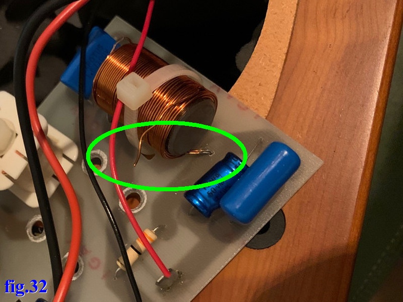 |
| The problem of a crossover wire broken by vibrations is highlighted in green. It is not a TDL crossover. With mouse-over instead, we see a coil that has come unglued and broken the wire. |
The repair is simple: you don't need to remove a turn, just scrape the enamelled wire for 3-5 mm, solder a rigid wire of similar thickness as an extension, and secure everything with neoprene glue, cable ties, silicone, etc.
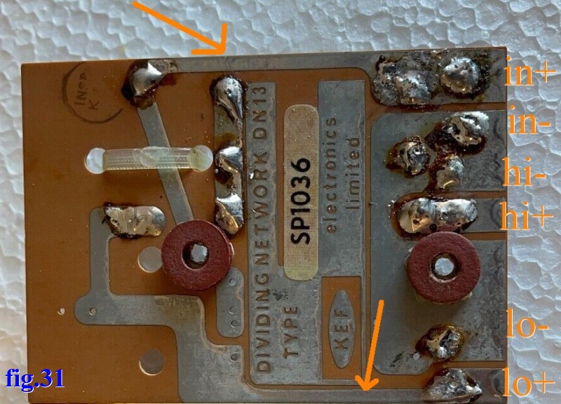
The inductors and large capacitors should be fixed in place with a view to at least 50 years of use (like the Tannoy GRF), spending a few extra euros (not fixed as poorly as the yellow inductor in fig.31).
 |
| Here is an excellent example of how to fix the components of a crossover. Here is an external version for the Solen Ananya cabinet. Here there is the high-resolution version. |
Capacitors
Certainly, capacitors are the components that suffer most from ageing: electrolytic capacitors dry out, paper and oil capacitors lose their oil, polystyrene capacitors cause problems at the wire connections, and polyxxx capacitors suffer from vibrations.
As already mentioned, it is better not to change anything just because some Guru says so. It is better to detach a lead and measure every capacitor in the right and left speakers, then make a table with all the measured values as shown in fig. 30 and compare them with the nominal values.
If you have some new capacitors of the same type, value and voltage available, you can also measure these and add them to the table.
Bear in mind that capacitors are subject to a tolerance of 20% if selected by the manufacturer, or 50% if not selected.
Capacitors not only have a capacity but also many other parameters (far more than a small instrument such as the one in fig. 30 can measure), so here are some rules for replacing them ..... only the defective ones.
If you need to replace the electrolytic capacitors, which are certainly not polarised, here is some sound advice: use the Mundorf BG or ECAP50 or ECAP70 series, which, as usual, are no longer manufactured, or AudynCap. If you have a choice, use the Plain version of the electrolytic capacitors as Fischer & Tausche ATBI or ATBIG.
Resistors
This is often where manufacturers focus their cost savings, perhaps with power at the limit, or commercial-grade quality. But... there are notable exceptions such as Tannoy and JBL.
Once again, the resistors must be measured one by one and the famous comparative table between L and R must be constructed, bearing in mind that a used resistor shows a tolerance of at least 10% before attempting a replacement.
Damage to resistors is also caused by vibrations or wattage overload. We often find resistors that appear to be in perfect condition, but when dismantled and measured, they give strange readings due to internal false contacts.
If we find differences between R and L in the values, or if the measurements are significantly different from the nominal value, or if the resistor is visually damaged, it MUST BE replaced. It is best to try to obtain the original value specified by the designer, perhaps using a parallel resistor.
There are two types of resistors used in crossovers: a) wirewound, b) metal oxide. The first are available with power ratings from a few watts to hundreds of watts, but apart from some special constructions, they have a parasitic inductive component. The second usually stop at 5 or 10W but are almost linear in their audio response.
 |
| It is best to use two different types of resistors in a crossover: on the right a green wirewound resistor, at the top various grey metal-oxide resistors. |
Pay attention to power dissipation; resistors must be mounted point-to-point in the air or raised 3-5 mm above the PCB using ceramic beads (but there are special ones available!).
Wirewound resistors are typically used in woofer and midrange filters as they have a parasitic inductive component. Metal oxide resistors are used in tweeter and supertweeter filters, which typically require low power, or in Zobel filters.
Now we need some advice on which brands to use, perhaps Dale, Mundorf, Ohmite, RoyalOhm, Sfernice, vintage Allen-Bradley, Welwyn, Holco, UTM Vitrohm, Beyschlag, but some Guru or Illuminated person would shoot down these suggestions.
Internal cable
All the TDLs I have seen use good conductors inside, whereas the IMFs use thinner but still adequate wires. You won't find expensive or boutique cables here, Mr Fried sold excellent sound, not dreams and chatter.
Some improvements could be made, but 2 mm for the woofer and 1.5 mm for the other drivers are sufficient. Be careful when changing the wires in the TDLs, as I have seen that these are soldered to both the crossover and the drivers. You will need to use a soldering iron with a maximum power of 50 W and be skilled at soldering.
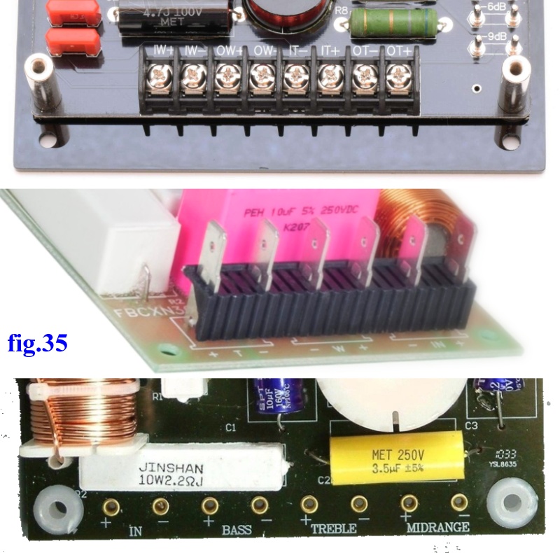 |
| How to attach the cables to the crossover? At the top with screw terminals, in the middle with fast-on connectors, at the bottom with soldering. |
If you want to change the internal cables in the speaker, perhaps to move the crossovers after separating the bass and treble, as in this A.O.S., I could suggest some cables that cost more per metre than the two speakers as ...... (but I'm not getting paid to advertise these cunning crafty people).
 |
| I usually use this cable in my speakers, the QED Connect, ultra-flexibility satin black 2.5mm OD, PVC jacket, with 37 strand 99.99% oxygen-free copper. |
The case, wood
There is very little that can be done for the cabinet. Wood care and the repair of defects and damage caused by use should be left to a skilled carpenter or cabinetmaker.
If the drivers have been dismantled frequently, the wood screw holes may be stripped. Some TDLs, like mine (and concert speakers), are fitted with 4mm spider nuts (tee nut), which, with a little patience, are easy to find and fit, giving much greater solidity.
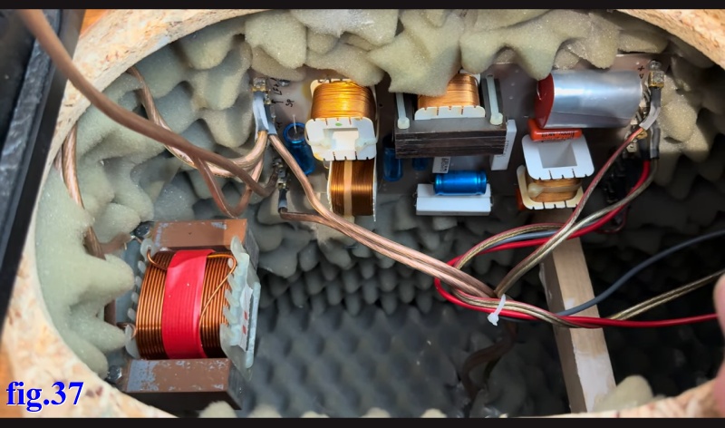 |
| Many thanks to the Danish user HiFi and DIY, who posted a video on YouTube showing the TDL Monitor Compact speakers opening up with a description of the components. |
Given the HiFi and DIY video TDL Electronics - Monitor Compact - a look inside let's study the speaker and offer some advice.
After analysing the entire speaker system, the only real problem could be point XIII above, which is really difficult to solve.
Now would be the time to measure the speakers, after a week of running in, but there is a problem:
The most interesting part of these speakers is their low-frequency response, but all response curves should be measured in an anechoic chamber, not just any anechoic lumber room, but an airship hangar that has been made anechoic.
Or modern technology helps us with Chirp, Gate, Squelch, Near-field, Windowing, to take quasi-anechoic measurements, but the real measurement can be taken outdoors on a 17.15 metre high pylon with nothing around it in order to read values up to 20Hz.
 |
| In a 2020 thread by Bikinpunk on diyAudio, this daredevil attempts to measure a bookshelf speaker in an open space. All of his tests are really interesting. |
But not knowing how to keep it suspended at almost 20 metres (on what?) or better still hanging from a crane (but then what about the microphone?), a TDL that you know how much it weighs... I give up. Maybe we can measure the total impedance, which is a bit easier.
The impedance of whole speaker
Finally, with this software, measuring impedance is even fun. Let's reassemble all the speakers, choose a suitable time so as not to irritate the neighbours, and run them in with pink noise at 2W for a couple of hours.
But .... we now know that the Whittaker-Nyquist-Kotelnikov-Shannon (WNKS) sampling criterion is sufficient to reproduce the sample frequency at a maximum frequency of 1/2 f, but not its shape and amplitude. The theory of Mishali and Eldar shows, among other things, that if the frequency locations are unknown, then it is necessary to sample at least at twice the Nyquist criteria; in other words, you must pay at least a factor of 2 f to obtain a better representation of the signal. More with a multiplier factor of 10x f we can reconstruct the shape and amplitude near perfect.
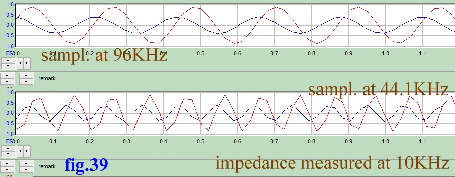 |
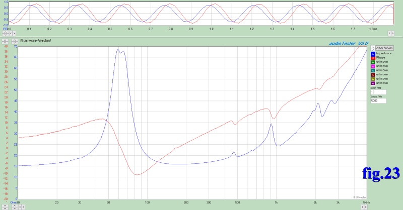
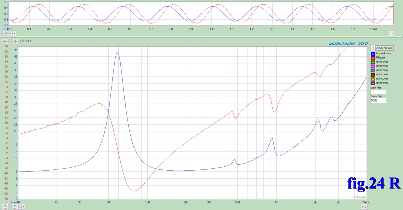
| We should have discussed this earlier, but before starting the impedance measurements, let's make sure that the card used can sample at least at 96KHz. In Figs. 23 and 24, the 5KHz limit allows us to use any card, but since we need to reach 20KHz, a 192KHz card is almost not suitable. Let's look at the waveforms produced by the same sound card above. With a sampling rate of 44 KHz, it does not look like a 10,000 Hz sine wave. |
With 96KHz sampling, we stop at 10,000 Hz, which already clearly shows the impedance of the tweeter.
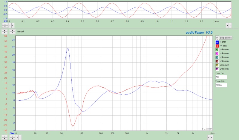 |
| In the impedance and phase graph of the left channel, we note problems due to the woofer now being out of specification and some good news. 1) these speakers really do reach 20Hz, see the resonance of the T.L., 2) the hump at 90 Hz shows us where the woofer resonance should end and there should be no hump if the woofer really resonated at 35Hz, see fig.25, 3) Now we understand that bunch of capacitors and inductors in the crossover (and even more so on the 4-way Monitor and the RSTL), the impedance and phase curves are easy for a good amplifier. Here there is the high-resolution version. |
A speaker like this deserves a woofer at its finest. We'll have to read the TDL woofer return to forever web page.
Below are the files mentioned on this page and available for download:
| In the last years at Universita' Degli Studi di Roma La Sapienza |
Dr. G. Visco already contract professor for Chemistry in Environment & Cultural Heritage into ---------> |
Laurea Degree Course of Sciences Applied to Cultural Heritage for Diagnostic and for Conservation |